Table of connectors – IEI Integration DP-LVDS User Manual
Page 3
3
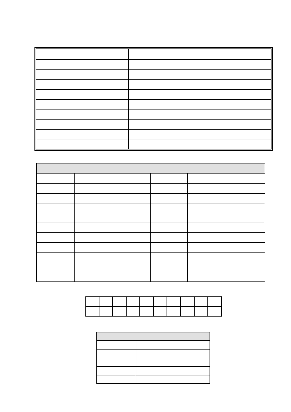
Table of Connectors
LABEL
FUNCTION
CN1
iEi Internal Display Port
PWR2
External Power Connector
LVDS2
LVDS Connector
INV2
LVDS Panel Voltage Supply
JP2
LVDS Voltage Selection
SW1
LVDS Resolution Selection
SW2
LVDS Backlight -
SW3
LVDS Backlight +
SW4
LVDS Power Switch
PWR2: LVDS Input Connector
PIN NO.
DESCRIPTION
1
+5V
2
GND
3
GND
4
+12V
CN1 : iEi Internal Display Port
PIN NO.
DESCRIPTION
PIN NO.
DESCRIPTION
1
+5V
2
DPD_OB_LANE1_N
3
DPD_OB_LANE1_P
4
GND
5
DPD_OB_LANE3_N
6
DPD_OB_LANE3_P
7
GND
8
AUX_CTRL_DET_D
9
GND
10
DDI1_HPD#
11
DPD_AUX_CTRL_P2
12
DPD_AUX_CTRL_N2
13
GND
14
DPD_OB_LANE2_P
15
DPD_OB_LANE2_N
16
GND
17
DPD_OB_LANE0_P
18
DPD_OB_LANE0_N
19
+3.3V
19
17
15
13
11
9
7
5
3
1
¡
20
18
16
14
12
10
8
6
4
2
See also other documents in the category IEI Integration Hardware:
- SPCIE-5100DX (180 pages)
- SPCIE-C2060 v1.01 (200 pages)
- SPCIE-C2060 v2.12 (212 pages)
- SPCIE-C2160 (204 pages)
- SPCIE-C2260-i2 (217 pages)
- ROCKY-3786 v4.0 (175 pages)
- ROCKY-3786 v4.10 (147 pages)
- PCIE-Q350 v1.00 (272 pages)
- PCIE-Q350 v1.12 (250 pages)
- PCIE-Q350 v1.20 (250 pages)
- PCIE-Q350 v1.30 (213 pages)
- PCIE-Q57A (159 pages)
- PCIE-G41A2 (151 pages)
- PCIE-Q670 v1.03 (206 pages)
- PCIE-Q670 v2.00 (205 pages)
- PCIE-H610 (181 pages)
- PCIE-Q870-i2 (217 pages)
- IOWA-LX-600 (159 pages)
- PCISA-945GSE v1.01 (207 pages)
- PCISA-945GSE v1.10 (190 pages)
- PCISA-9652 v1.00 (232 pages)
- PCISA-9652 v1.01 (232 pages)
- PCISA-PV-D4251_N4551_D5251 (145 pages)
- PICOe-945GSE (197 pages)
- PICOe-GM45A (198 pages)
- PICOe-PV-D4251_N4551_D5251 v1.00 (154 pages)
- PICOe-PV-D4251_N4551_D5251 v1.10 (154 pages)
- PICOe-PV-D4251_N4551_D5251 v1.11 (155 pages)
- PICOe-B650 (156 pages)
- PICOe-HM650 (174 pages)
- HYPER-KBN (139 pages)
- SPXE-14S (3 pages)
- SPXE-9S v1.00 (5 pages)
- SPXE-9S v1.1 (6 pages)
- SPE-9S v1.00 (4 pages)
- SPE-9S v1.1 (5 pages)
- SPE-6S (3 pages)
- SPE-4S (4 pages)
- PE-6SD3 (4 pages)
- PE-6SD2 v4.0 (4 pages)
- PE-6SD2 v2.10 (3 pages)
- PE-6SD (3 pages)
- PE-6S3 v1.0 (2 pages)
- PE-6S3 v4.0 (4 pages)
- PE-6S2 (4 pages)