2 vga monitor connection, Figure 5-18: lan connection – IEI Integration PCISA-9652 v1.00 User Manual
Page 118
PCISA-9652 Half-Size CPU Card
Page 98
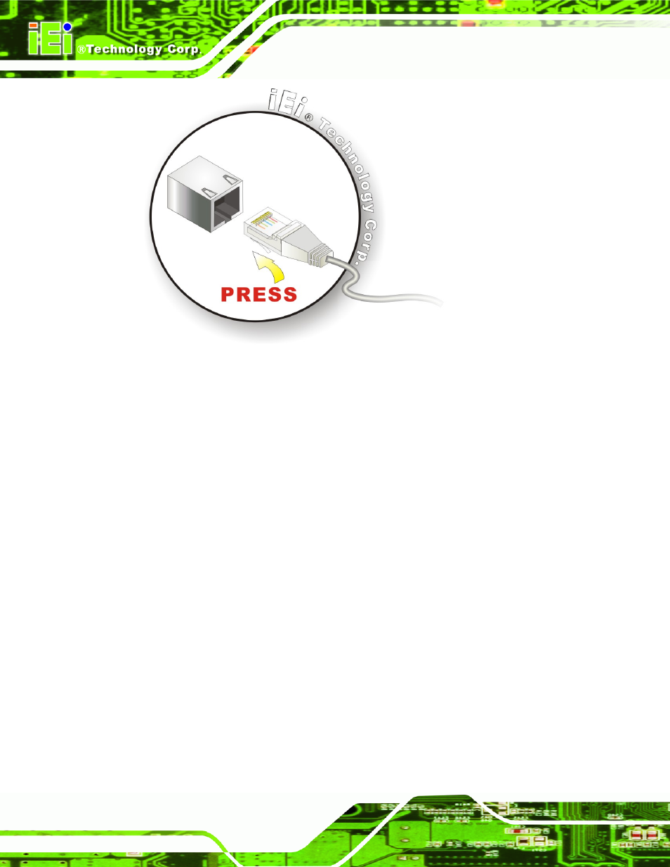
Figure 5-18: LAN Connection
Step 3:
Insert the LAN cable RJ-45 connector. Once aligned, gently insert the LAN
cable RJ-45 connector into the on-board RJ-45 connector.
Step 0:
5.7.2 VGA Monitor Connection
The PCISA-9652 has a single female DB-15 connector on the external peripheral interface
panel. The DB-15 connector is connected to a CRT or VGA monitor. To connect a monitor
to the PCISA-9652, please follow the instructions below.
Step 1:
Locate the female DB-15 connector. The location of the female DB-15
connector is shown in Chapter 3.
Step 2:
Align the VGA connector. Align the male DB-15 connector on the VGA screen
cable with the female DB-15 connector on the external peripheral interface.
Step 3:
Insert the VGA connector
.
Once the connectors are properly aligned with the
insert the male connector from the VGA screen into the female connector on the
PCISA-9652. See Figure 5-19.