3 vga monitor connection, Figure 4-17: usb device connection – IEI Integration SPCIE-C2060 v2.12 User Manual
Page 75
SPCIE-C2060 PICMG 1.3 CPU Card
Page 59
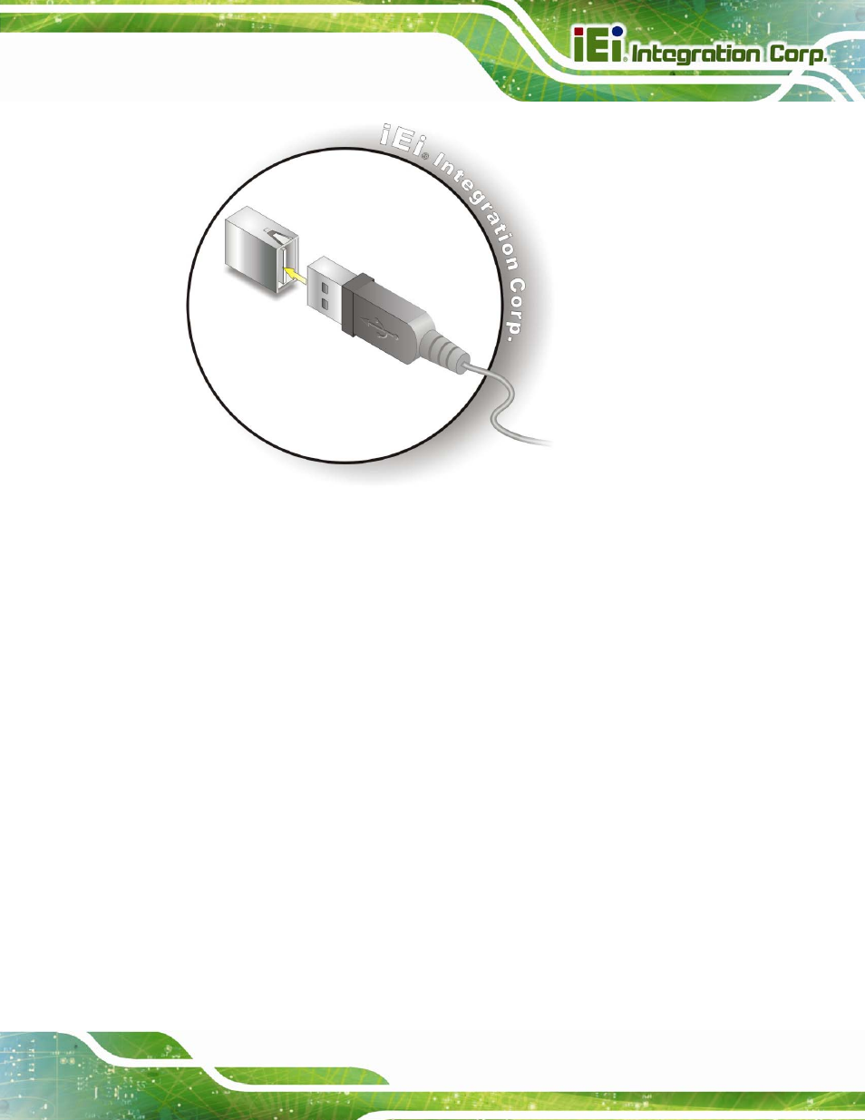
Figure 4-17: USB Device Connection
Step 3:
Insert the device connector. Once aligned, gently insert the USB device
connector into the on-board connector.
4.6.3 VGA Monitor Connection
The SPCIE-C2060 Series has a single female DB-15 connector on the external peripheral
interface panel. The DB-15 connector is connected to a CRT or VGA monitor. To connect
a monitor to the SPCIE-C2060 Series, please follow the instructions below.
Step 1:
Locate the female DB-15 connector. The location of the female DB-15
connector is shown in Chapter 3.
Step 2:
Align the VGA connector. Align the male DB-15 connector on the VGA screen
cable with the female DB-15 connector on the external peripheral interface.
Step 3:
Insert the VGA connector
.
Once the connectors are properly aligned with the
insert the male connector from the VGA screen into the female connector on the
SPCIE-C2060 Series. See Figure 4-18.