Dash panel gauge installation (cont’d), Inline pressure regulator installation – VIAIR X'Treme Duty OBA User Manual
Page 8
USER MANUAL
X’TREME DUTY ONBOARD AIR SYSTEM
DASH PANEL GAUGE INSTALLATION (CONT’D)
7. Connect to Power Source:
Before connecting the power wire to a power source, check to make sure that the ON/OFF switch on
the dash panel gauge is in the OFF position. Connect the ring terminal of the power wire to power source.
(This is the wire described in Step 4, which is connected to the ON/OFF switch of the dash panel gauge.)
8. Testing Your Onboard Air System:
Your Onboard Air System installation is now complete. Run the compressor to build pressure in the air tank.
When air pressure reaches the pressure switch cut out pressure, the compressor will shut off. Inspect all air
line connections for leaks with soap and water solution and spray with a spray bottle onto connections
to check for leaks. If leaks are detected, push air line may not be cut squarely or pushed all the way in.
Fix connections as needed. Periodically check your system’s fitting in this manner should your compressor
turn on more often than normal without frequent air use.
INLINE PRESSURE REGULATOR INSTALLATION
(USE CONTENTS OF PARTS PACKAGE #6)
Your Onboard Air System comes complete with an adjustable inline air pressure regulator that may be
used to regulate the pressure in your air tank down to any pressure below 150 PSI. This is especially
useful for installations that will supply air to a locking differential, or may be used to operate air tools.
Never attempt to use the regulator to adjust any tank pressure over 150 PSI, since the component is
only rated to a maximum of 150 PSI.
1. Mounting the Inline Pressure Regulator:
Select a mounting location with a rigid mounting surface such as the bottom edge of a chassis.
Use the inline pressure regulator mounting bracket as a template to mark the two mounting points to be drilled.
Carefully drill the two holes as marked, but do mount the Pressure Regulator at this time.
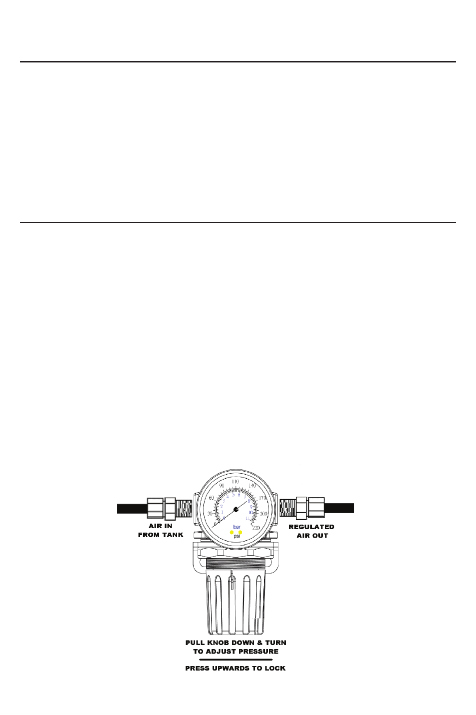
2. Air Line Connections to Inline Pressure Regulator:
Use a 1/4” NPT compression fitting on the “IN” side of the regulator receiving air from the air tank.
On the “OUT” side of the regulator, you may install a 1/4” NPT quick connect coupler, or use another 1/4” NPT
compression fitting to route the air line to the source of the item that pressure is being regulated to. If you are
plumbing to air locking differentials, we have included two 1/8” BSP Female to 1/4” NPT Male Adapters for this
use. You may require a T-fitting (not included), depending on your application.
3. Adjusting pressure 0-150 PSI:
The pressure regulator knob locks when pushed towards the unit. To adjust pressure, simple pull knob
away from the regulator body and adjust as needed. Always lock the adjustment knob in place before using
pressure-adjusted air supply to keep pressure regulated at a fixed pressure. (See Figure 2)
Pressure Regulator Diagram:
(Figure 2)