Teledyne LeCroy DFP2 - Digital Filter Package 2 User Manual
Page 8
6
ISSUED:
June 2013
923134 Rev A
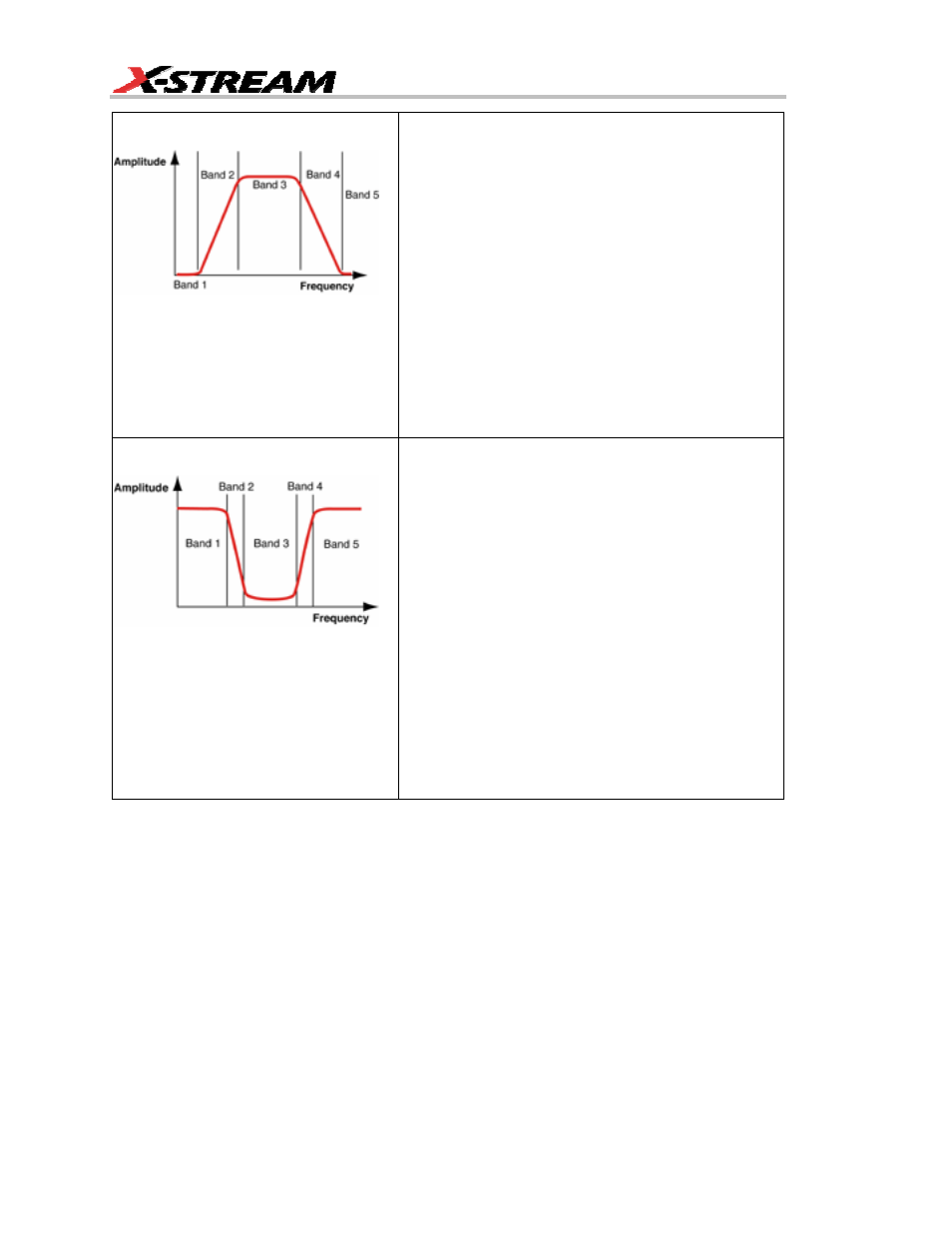
Band-pass Filter
Band-pass filters are useful for emphasizing a selected
frequency band. Sample applications include radio
channel identification, broadband transmission, ADSL,
clock generators (i.e., eliminating the central frequency
and displaying harmonics only), and
telecommunications (Jitter measurement over a
selected frequency range).
Band 1: First Stop Band — DC to bottom of first
transition region; highly attenuated.
Band 2: First Transition Region — lower corner minus
width to lower corner; decreasing attenuation.
Band 3: Pass Band — signal passes unattenuated.
Band 4: Second Transition Region — upper corner to
upper corner plus width; increasing attenuation.
Band 5: Second Stop Band — signal highly attenuated.
Band-stop Filter
Band-stop filters are useful for eliminating a narrow
band of frequencies. Sample applications include
medical equipment, such as ECG monitors where the
dominant ripple at 50/60 Hz is rejected, leaving the low
energy biological signals intact. Digital troubleshooting:
the inherent frequency of the switched power supply is
blocked, revealing power line voltage drops and
glitches caused by the system clock generator.
Band 1: First Pass Band — DC to bottom of first
transition region; signal passes unattenuated.
Band 2: First Transition Region — lower corner minus
width to lower corner; increasing attenuation.
Band 3: Stop Band — signal is highly attenuated.
Band 4: Second Transition Region — upper corner to
upper corner plus width; decreasing attenuation.
Band 5: Second Pass Band — signal passes
unattenuated.