Superwinch LT2000 – 907 kgs/12V User Manual
Page 3
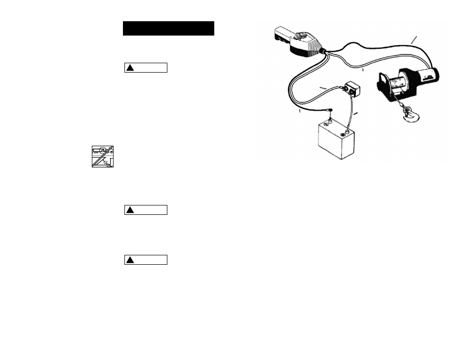
Route the two wires from the
motor to the switch. Route the two
wires from the switch to the bat-
tery. Attach the circuit breaker to
battery end of the red wire. Wrap
the circuit breaker with electrical
tape to prevent accidental short cir-
cuits.
Apply several layers of electrical
tape where wiring may come into
contact with sharp metal parts of
the vehicle to prevent insulation
abrasion or cutting.
Attach the circuit breaker directly to
the battery positive terminal and
reattach the terminal to the battery.
Connect the remaining black switch
wire to the battery negative terminal
and connect the terminal to the
battery.
Step (5)
Pull and turn (see Figure 8) the
freespool clutch knob to the “Free”
position. Pull several feet of wire
rope off the drum. Return the clutch
knob back to the “Engaged” posi-
tion. Activate the winch in Cable
Out momentarily to check drum
rotation direction. If the drum
rotates in the wrong direction,
recheck your wiring.
FREESPOOL OPERATION
Pull and turn the clutch knob to the
“Free ” position as shown in Figure
8. If there is a load on the wire
rope, the clutch knob may not pull
out easily. DO NOT FORCE THE
CLUTCH KNOB. Release tension on
the clutch by jogging out some of
the wire rope. Release the clutch
and pull out the wire rope and
secure to anchor or load. Check that
there are at least five (5) turns of
wire rope left on the drum. Re-
engage the drum by returning the
clutch knob to the “Engaged” posi-
tion. (See Figure 8).
4
5
20. ALWAYS DISCONNECT WINCH
POWER LEADS TO BATTERY
BEFORE WORKING IN OR
AROUND THE WINCH DRUM so
that the winch cannot be turned
on accidentally.
21. When moving a load, slowly
take up the wire rope slack until
it becomes taut. Stop, recheck
all winching connections. Be
sure the hook is properly seated.
If a nylon sling is used, check the
attachment to the load.
22. When using your winch to move
a load, place the vehicle trans-
mission in neutral, set vehicle
brake, and chock all wheels.
23. DO NOT USE THE WINCH TO
HOLD LOADS IN PLACE.
Use other means of
securing loads such
as tie down straps.
24. USE ONLY FACTORY APPROVED
SWITCHES, REMOTE CONTROLS
AND ACCESSORIES. Use of non-
factory approved components
may cause injury or property
damage and could void your
warranty.
25. DO NOT MACHINE OR WELD
ANY PART OF THE WINCH. Such
alterations may weaken the
structural integrity of the winch
and could void your warranty.
26. DO NOT CONNECT WINCH TO
EITHER 110V AC HOUSE CUR-
RENT OR 220V MAINS AS WINCH
BURNOUT OR FATAL SHOCK
MAY OCCUR.
27. Never allow shock loads to be
applied to winch or wire rope.
28. Use caution when pulling or
lowering a load up and down a
ramp or incline. Keep people,
pets and property clear of the
path of the load.
Correct installation of your winch is
required for proper operation.
This winch MUST
be mounted
with the wire rope in the under-
wind direction. Improper mounting
could damage your winch and void
your warranty.
Step (1)
Install mounting kit or structural
support for winch.
Step (2)
Mount the winch to the mounting
kit base plate or to the mount that
you have designed. Typical mount is
to a flat surface capable of han-
dling the loads.
The M8 x 1.25 x 30mm mounting
bolts supplied are the correct length
for use with a 1/4" (6.3mm) thick
mounting plate.
Do not
substitute
any strength grade weaker than
ISO grade 4.6
Step (3)
Disconnect the vehicle battery leads.
Batteries contain
gasses which are
flammable and explosive. Wear eye
protection during installation and
remove all metal jewelry. Do not
lean over battery while making
connections.
Step (4)
Refer to Figure 7 for wiring
diagram.
WARNING
!
WARNING
!
WARNING
!
I N S T A L L A T I O N
Figure 7
Red
Red
Black
Red
Black