Installing counter stations – Audio Authority Series 1500 User Manual
Page 6
6 Audio Authority
®
Series 1500 Installer’s Reference Guide
Audio Authority
®
Series 1500 Installer’s Reference Guide 7
Installing Counter Stations
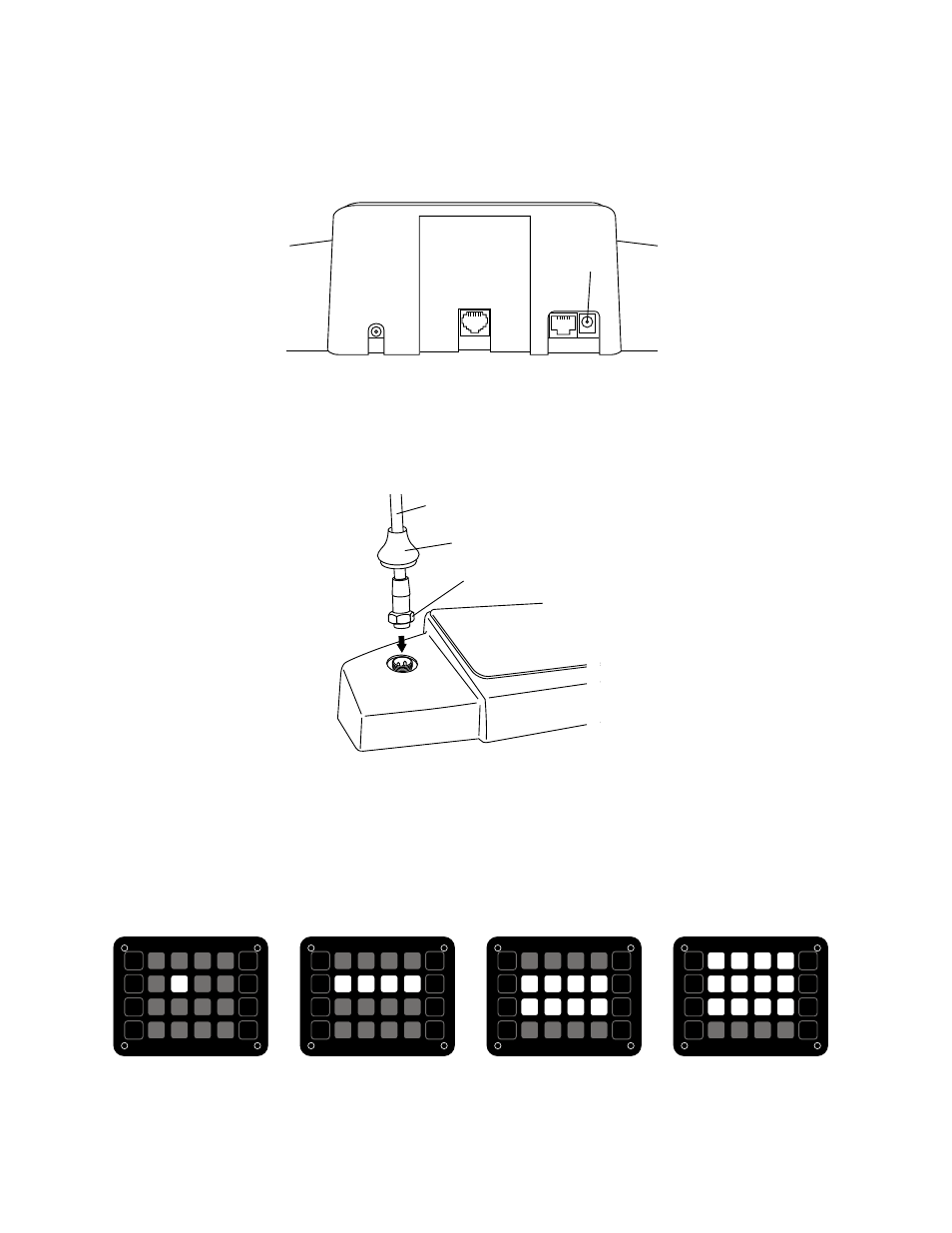
1. Unpack each Model 1500 Counter Station and, if applicable, slide a 1502 Video Display onto it (the rear panel must
first be slid out and discarded). Plug the 1502 cable into the matching port on the 1500.
BOOT
NUT
MICROPHONE STALK
HEADSET
1502 VIDEO
DISPLAY
CONNECTION
CAT 5
CABLE
POWER
PACK
Single Lane (1x1) Default
1509 or 1510 Default
1511 Default
1512 Default
2. Attach the field-replaceable microphone, tightening the nut securely with a 18mm open end wrench, and tuck its
rubber boot firmly into place.
3. Plug the Cat 5 cable from the hub into the Hub port of each 1500 and connect the power supply to the Power jack.
4. Install the desired keyboard inlays into the Model 1500. The hub configuration sets the default key layout
automatically (see examples below). You can choose to color-code by the carrier color or label the keys numerically.
For one-on-one systems, place a lane color chip in the position shown. Place blank, black chips in all the other
positions. For multi-lane systems, place the desired chips in the active lane positions as indicated and black chips
in the other positions. Save the unused key chips on the premises for future changes or expansion.
HUB
PORT