Troubleshooting, Part numbers – LEESON 143-5TC Double C-Face Coupler User Manual
Page 4
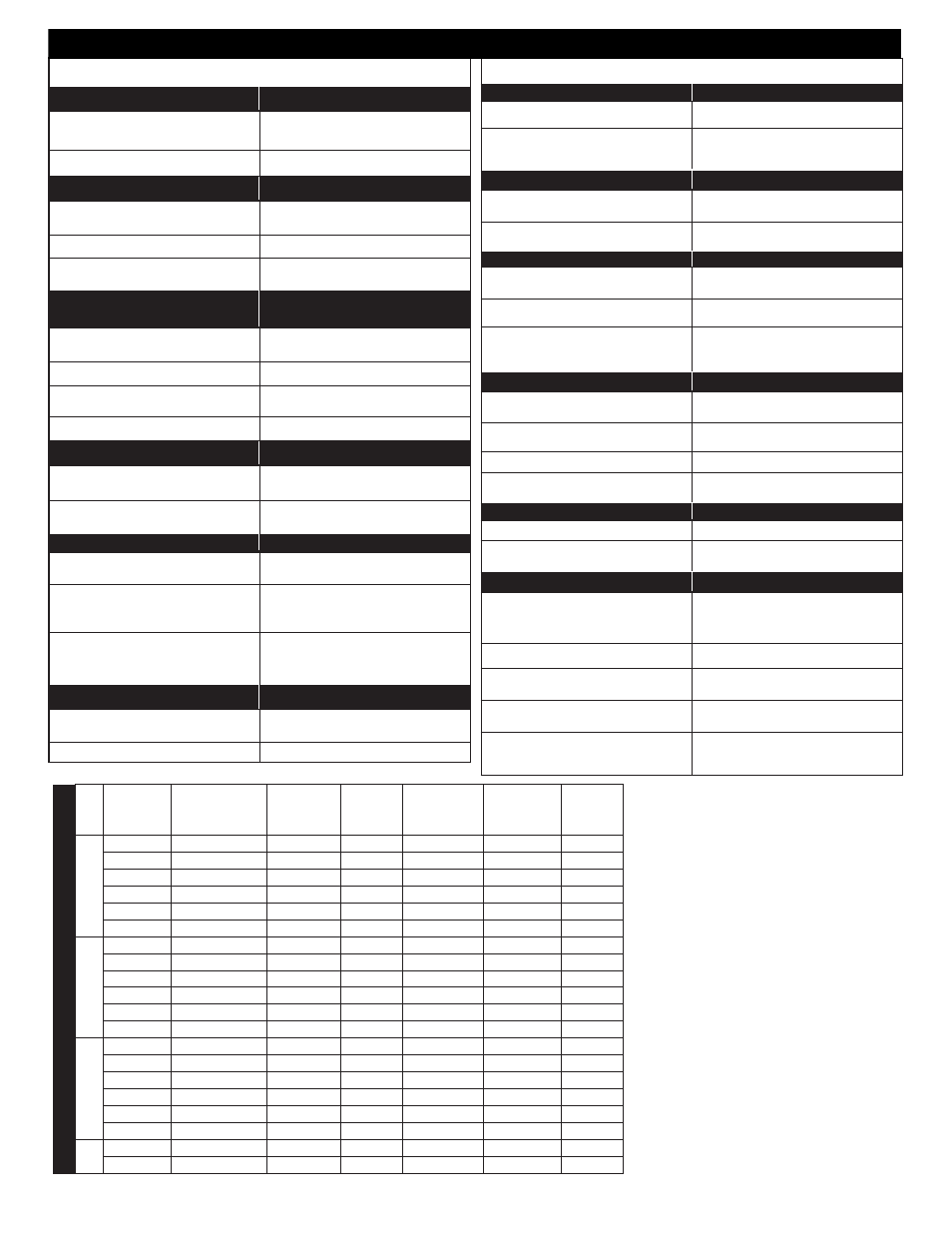
T
orque
lb. f
t.
Leeson
Part
Number
Stearns
Part
Number
Brake Coil
Rating (VAC)
NEMA
Enclosure
Brake Bore/
Shaft Diameter
(X/U)
NEMA
Frame Size
Dimension
A
3
175563.00
1056711051PF
115/208-230
2
5/8” / 5/8”
56C
4.91”
175564.00
1056711051QF
208-230/460
2
5/8” / 5/8”
56C
4.91”
175565.00
1056711051NF
575
2
5/8” / 5/8”
56C
4.91”
175566.00
1056714051PF
115/208-230
4X
5/8” / 5/8”
56C
4.94”
175567.00
1056714051QF
208-230/460
4X
5/8” / 5/8”
56C
4.94”
175568.00
1056714051NF
575
4X
5/8” / 5/8”
56C
4.94”
6
175569.00
1056721081PF
115/208-230
2
7/8” / 5/8”
56C/143-5TC
4.91”
175570.00
1056721081QF
208-230/460
2
7/8” / 5/8”
56C/143-5TC
4.91”
175571.00
1056721081NF
575
2
7/8” / 5/8”
56C/143-5TC
4.91”
175572.00
1056724081PF
115/208-230
4X
7/8” / 5/8”
56C/143-5TC
4.94”
175573.00
1056724081QF
208-230/460
4X
7/8” / 5/8”
56C/143-5TC
4.94”
175574.00
1056724081NF
575
4X
7/8” / 5/8”
56C/143-5TC
4.94”
10
175575.00
1056731081PF
115/208-230
2
7/8” / 5/8”
56C/143-5TC
4.91”
175576.00
1056731081QF
208-230/460
2
7/8” / 5/8”
56C/143-5TC
4.91”
175577.00
1056731081NF
575
2
7/8” / 5/8”
56C/143-5TC
4.91”
175578.00
1056734081PF
115/208-230
4X
7/8” / 5/8”
56C/143-5TC
4.94”
175579.00
1056734081QF
208-230/460
4X
7/8” / 5/8”
56C/143-5TC
4.94”
175580.00
1056734081NF
575
4X
7/8” / 5/8”
56C/143-5TC
4.94”
15
175581.00
1056741071QF
208-230/460
2
7/8” / 7/8”
143-5TC
4.91”
175582.00
1056744071QF
208-230/460
4X
7/8” / 7/8”
143-5TC
4.94”
P
ART NUMBERS
COIL FAILURE
SUPPLY VOLTAGE CAUSE
SUPPLY VOLTAGE CORRECTION
Line voltage >110% of coil rating
Reduce voltage or replace with
proper rated coil
Excessive voltage drop during inrush time Increase current rating of power supply.
WIRING CAUSE
WIRING CORRECTION
Leadwires interfering with plunger pull-in
Reroute wiring away from plunger and
other moving components.
Excessive voltage drop during inrush time Increase leadwires size from power supply
Coil leadwire shorted to ground
Replace coil or leadwire and protect with
wire sleeving
SOLENOID ASSEMBLY CAUSE
SOLENOID ASSEMBLY
CORRECTION
Plunger not seating flush against
solenoid frame
Loosen solenoid mounting screws and
reposition frame to allow full face contact
Plunger cocked in coil preventing pull-in
Realign solenoid frame
Excessive solenoid/plunger wear at
mating surface
Replace solenoid assembly
Broken shading coils
Replace solenoid assembly
WORN PARTS CAUSE
WORN PARTS CORRECTION
Excessive wear of solenoid link arm
and/or shoulder bolt
Replace link arm and link bolt; also
inspect plunger thru-hole for elongation
Plunger guides worn down and interfering
with plunger movement
Replace guides
APPLICATION CAUSE
APPLICATION CORRECTION
Machinery cycle rate is exceeding brake
rating
Reduce brake cycle rate or use
alternate control method
High ambient temperature (>110%) and
thermal load exceeding coil insulation
rating
Use Class H rated coil and /or find
alternate method of cooling brake
Brake coil wired with windings of an
Inverter motor or other voltage/current
limiting device
Wire coil to dedicated power source with
instantaneous coil rated voltage
MISCELLANEOUS CAUSE
MISCELLANEOUS CORRECTION
Wrong or over tightened torque
Replace with proper spring or refer to
Installation section for proper spring height
Excessive air gap
Reset, refer to Installation Section 4
EXCESSIVE WEAR / OVERHEATING
AIR GAP CAUSE
AIR GAP CORRECTION
Low solenoid air gap
Reset air gap (refer to Air Gap
Adjustment)
Disc pack dragging
Inspect endplate, hub and discs for dirt,
burrs, wiring and other sources of interfer-
ence preventing disc “float”
CYCLE RATE CAUSE
CYCLE RATE CORRECTION
Brake “jogging” exceeding coil cycle rate
Reduce cycle rate or consider
alternate control method
Thermal capacity is being exceeded
Reduce cycle rate, use alternate control
method or increase brake size
ALIGNMENT CAUSE
ALIGNMENT CORRECTION
Broke endplate not concentric to motor
C-Face
Motor register must be within .004” on
concentricity;
Motor shaft runout is excessive
Must be within .002”; runout; consult
motor manufacturer
Brake is being operated on a incline
greater than 15° above or below
horizontal
Vertical separator springs must be used to
prevent discs from becoming cocked
WORN PARTS CAUSE
WORN PARTS CORRECTION
Friction disc excessively worn (disc can
wear to 1/2 original thickness or .093”)
Replace friction discs.
Endplate, stationary disc or pressure
plate warped
Replace warped or worn component
Linkages and/or pivot pins worn
Replace all worn components
Motor shaft endfloat excessive
Endfloat must not exceed .020”;
consult motor manufacturer
HUB CAUSE
HUB CORRECTION
Burr on hub interfering with disc “float”
File off burr
Set screw backed out and interfering with
disc
Retighten set screw; use Loctite® 242 to
help secure
MISCELLANEOUS
MISCELLANEOUS
Solenoid plunger not pulling completely
Check line voltage (±10% of
nameplate rating) or replace worn
solenoid assembly
Wiring is restricting disc pack movement
Reroute wiring
Excessive stop time
(2 seconds or greater)
Increase brake size/torque or use alter-
nate control method
High Ambient temperature
(in excess of 110°F)
Reduce cycle rate or use alternate
method of cooling
Moisture in brake
Remove drain plug (WASHGUARD
brakes only). After fluid has drained
replace plug
TROUBLESHOOTING
4