Exploded view, Top aligned bottom aligned center aligned – LEESON Sub-Micro DIN Rail Kit User Manual
Page 2
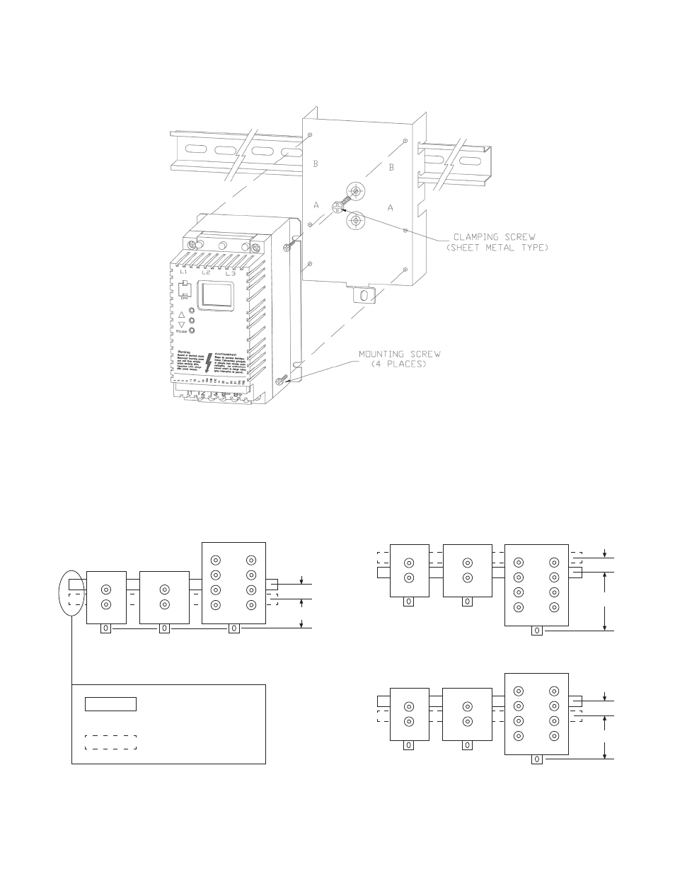
EXPLODED VIEW
MOUNTING POSITIONS
The diagrams below illustrate the different mounting positions that are possible with the DIN Rail Mounting Kit. Drives can be
mounted next to each other with the top, bottom, or center of the drives aligned. The diagrams indicate recommended and
alternate mounting positions to use on each DIN Rail Mounting Bracket to achieve the desired alignment.
TOP ALIGNED
BOTTOM ALIGNED
CENTER ALIGNED
RECOMMENDED DIN
RAIL POSITION
ALTERNATE DIN RAIL
POSITION
5.13"
1.00"
5.89"
3.75"
4.63"
3.13"
1.00"
4.13"
1.00"
LEESON Electric
LEESON Electric
LEESON Electric
LEESON Electric
LEESON Electric • 2100 Washington St. • Grafton, WI 53024 • Ph: (262) 377-8810 • Fax: (262) 377-9025 • www.leeson.com