J501, L1 l 2 – LEESON Mounting Instructions for FHP Series User Manual
Page 4
4
Leeson FHP Series PCM Adder Board 175324.00 Mounting Instructions
2100 Washington Street
Grafton, WI 53024-0241, U.S.A.
TEL: (262) 377-8810 FAX: (262) 377-9025
Document number 250-0367, Revision 0
Printed in the U.S.A. - January 2003
Copyright © 2003 by LEESON Electric - All rights reserved. No part of this document may be reproduced or transmitted in any form without
written permission from LEESON Electric. The information and technical data in this document are subject to change without notice.
LEESON Electric and its Divisions make no warranty of any kind with respect to this material, including, but not limited to, the implied
warranties of its merchantability and fitness for a given purpose. LEESON Electric and its Divisions assume no responsibility for any errors
that may appear in this document and make no commitment to update or to keep current the information in this manual.
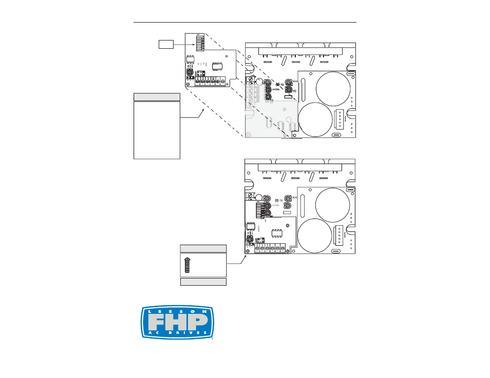
SECURE THE
PCM ADDER
BOARD WITH
THE 6-32 x 1 5/16"
PHILLIPS SCREW.
S T E P # 8
V
U
W
J501
C501
C502
TH501
L
1
L
2
1
1
5
V
230
V
DECEL
D
JMP501:INPUT R
A
1:0-5V
D
2:0-10
V
3
:4
-20M
J
MP
502
:INP
U
T TYP
E
TB5
01
2-3:
C
URREN
T
1-2:V
O
LTA
GE
POSITION THE PCM
ADDER BOARD OVER
THE BOTTOM BOARD
AS SHOWN.
NOTE: First align the
bottom holes of J501 (on
the PCM adder board) with
the 6 pin header installed
on the bottom board. The
PCM adder board will
snap into place at J501
and the two standoffs.
S T E P # 7
TB501
V
U
W
J501
C501
C502
TH501
L
1
L
2
1
1
5
V
230
V
TQ
DECEL
S2
S
3
D
0
1:INPUT RAN
GE
1:0-5VD
C
2:0
10VDC
JMP5
02
:INPUT TYP
E
TB5
01
2-3:
C
URREN
T
1-2:V
O
LTA
G
E
J501
INSTALLATION COMPLETE.
IC502
J501
JMP501