Jmp504, Jmp505 – LEESON FHP Series NEMA 4x 175326 Quick Start Guide User Manual
Page 2
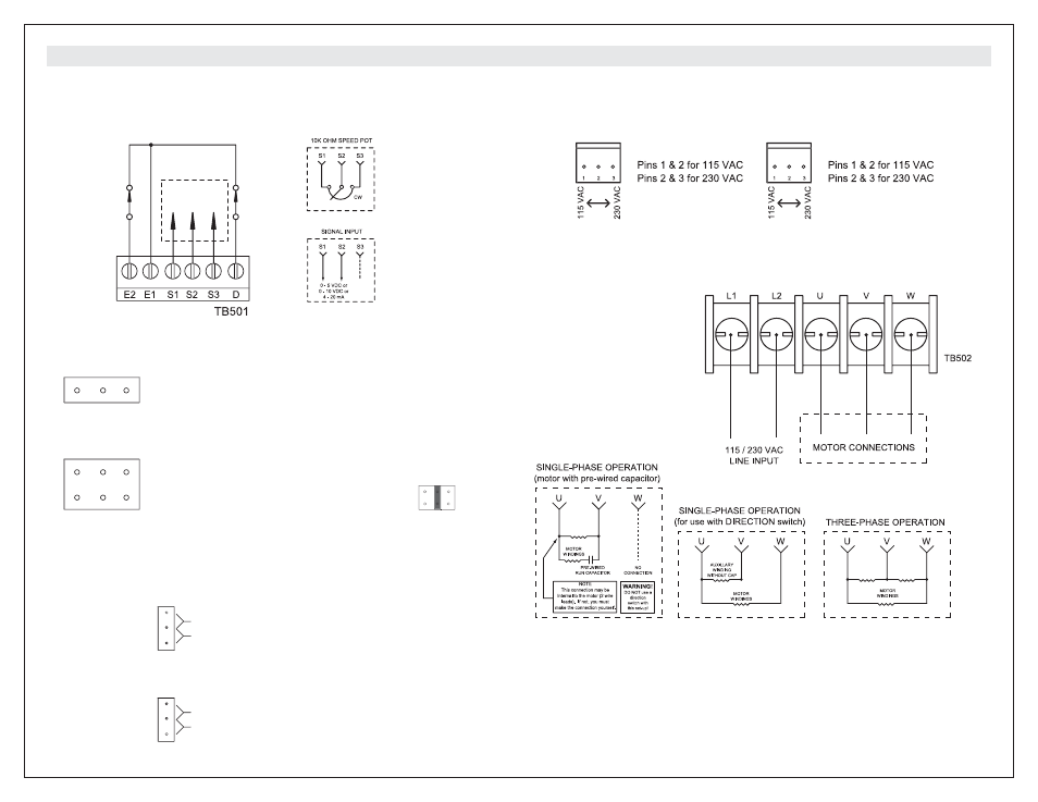
STEP #4
Configure jumpers JMP501 and JMP502 on the bottom board for 115 or 230 VAC Power Input.
JMP502
JMP501
STEP #2
Configure jumpers JMP504 and JMP505 on the top board for the appropriate signal input.
JMP504
1 2
3
1 2
3
JMP505
1 2
3
JMP505
JMP504 (on top board)
Pins 1 & 2 for Voltage Input, or using a speed pot.
Pins 2 & 3 for Current Input
JMP505 (on top board)
Pins in Column 1 for 0 - 5 VDC Voltage Input,
or using a speed pot
Pins in Column 2 for 0 - 10 VDC Voltage Input
Pins in Column 3 for 4 - 20 mA Current Input
example:
STEP #3
Configure jumpers JMP503 on the bottom board and JMP506 on the top board.
JMP503
JMP503 (on bottom board)
Pins 1 & 2 to Trip
Pins 2 & 3 to Restart
TRIP: Drive has a low voltage fault & must
be manually re-enabled to restart.
RESTART: Drive has a low voltage fault &
will momentarily stop then auto-restart
when input voltage returns to minimum level.
UV TRIP
RESTART
1
2
3
JMP506
JMP506 (on top board)
Pins 1 & 2 to Brake
Pins 2 & 3 to Coast
BRAKE
COAST
1
2
3
C O N N E C T I O N S
STEP #5
Connect motor leads of a 3-
phase motor to U, V, and W
(TB502 on BOTTOM board)
using 14 - 16 AWG wire as
shown in the figure below.
STEP #6
Connect 115 or 230 VAC power
input using 12 AWG wire.
NOTE: LEESON strongly
recommends installing an
emergency stop switch on both
the L1 and L2 inputs.
STEP #1-skip this step if provided FWD/OFF/REV and speed potentiometer will be used.
Otherwise disconnect factory-wired connections from the FWD/OFF/REV switch and speed
potentiometer. Connect the enable/disable switch, direction switch, and speed potentiometer or
signal input to TB501 on the TOP board using 20 - 24 AWG wire as shown below.
DIRECTION
SWITCH
ENABLE/DISABLE
SWITCH
(open to disable)
NOTE:
The factory-wired speed
potentiometer on the
case cover must be
disconnected prior to
wiring to a signal input
TO SPEED POT
OR SIGNAL INPUT
Copyright 2003 by LEESON Electric - All rights reserved. No part of this document may be reproduced or transmitted in any form without
written permission from LEESON Electric. The information and technical data in this document are subject to change without notice. LEESON
Electric makes no warranty of any kind with respect to this material, including, but not limited to, the implied warranties of its merchantability
and fitness for a given purpose. LEESON Electric assumes no responsibility for any errors that may appear in this document and make no
commitment to update or to keep current the information in this document.
kc0504
L E E S O N E l e c t r i c
w w w . l e e s o n . c o m
2100 Washington Street, Grafton, WI 53024-0241, USA
Phone: 262-377-8810 Fax: 262-377-9025
Document Number: 250-0389, Revision 0; Printed in the U.S.A. - May 2004