Rear panel, Pam-120a) – Inter-M PAM-480A User Manual
Page 7
PUBLIC ADDRESS AMPLIFIER
5
PAM-120A/340A/480A
Rear Panel
Rear Panel
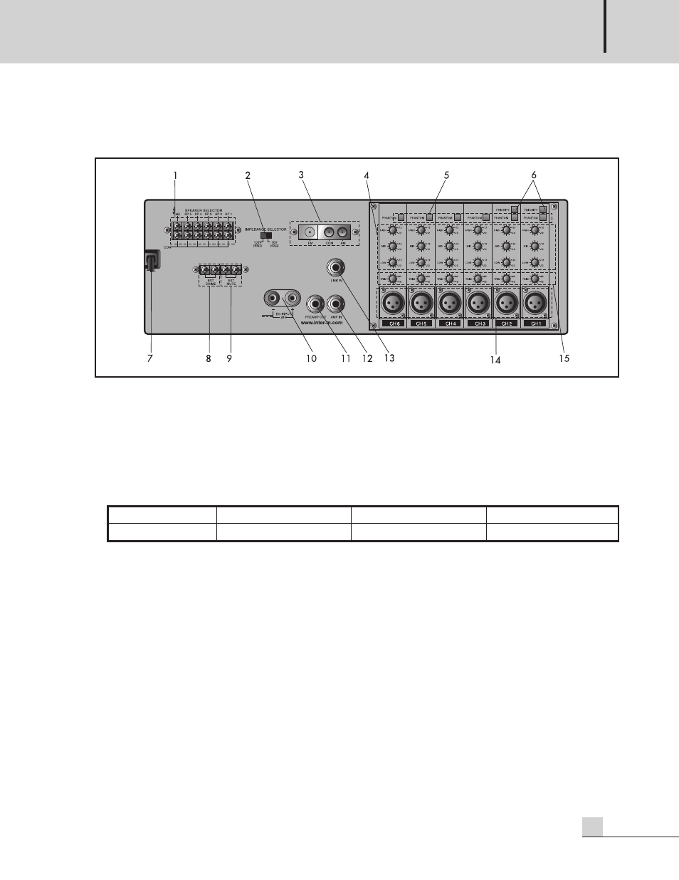
(PAM-120A)
1. SPEAKER OUTPUT TERMINAL STRIP
Connect up to five individual speakers to this strip.
Impedances for 4Ω, 70V and 100V operation are shown below. Connect speakers whose combined
impedance is equal to or higher than the rated output impedance, as shown below.
2. IMPEDANCE SELECTOR
Selects between high impedance operation at 70V or 100V distributed systems. Note that when speakers are
connected to the 4Ω terminal, this switch is inactive.
3. ANTENNA CONNECTOR (OPTIONAL)
This terminal is used to connect the antenna, when used with the optional PAM-T AM/FM Tuner module.
4. EQ CONTROLS
Three-band equalization control provides ±12dB of cut (decrease) or boost (increase) over the high, mid and
low frequency ranges of the individual channel signals.
HIGH – 10kHz, ±12dB MID – 1kHz, ±12dB LOW – 100Hz, ±12dB
5. PHANTOM POWER SWITCH
This switch turns the phantom power supply on or off for all channels. When the switch is turned on, +22V DC
power is supplied to pins 2 and 3 of each channel’s input connector.
Use phantom power when connecting condenser microphones, which require an external power supply.
NOTE:
It is safe to connect most modern dynamic microphones or line level devices to the channel inputs
when phantom power is activated. However, some older ribbon microphones may be damaged by
phantom power, and certain unbalanced line level devices may malfunction or produce an audible
hum when phantom power is active.
MODEL
4Ω
70V
100V
PAM-120A
22V
42Ω
83Ω