Inter-M PAM-480A User Manual
Page 10
PUBLIC ADDRESS AMPLIFIER
8
PAM-120A/340A/480A
5. PRIORITY SWITCH
When selected, these switches will give priority to Channels 1 and/or 2 over all other channels and audio inputs.
6. AC POWER INPUT
Connect a standard three-pin AC cable to your AC outlet.
7. EM
When EM switch is connected and pressed in fire or other emergencies, EM broadcasting stored in VOICE IC
is outputted.
* Remove an input jack from AMP IN not to affect Emergency signal to be played or adjust the main audio
signal to adequate level for emergency broadcasting.
8. EXT CHIME
When these two terminals are shorted by wired remote (see item 14 above), the four-tone chime circuitry is
activated.
9. EXT MUTE
When these two terminals are shorted by wired remote (see item 14 above), signals from Input Channels 3-6
and any optional modules are muted. Signals from Channel 1, Channel 2, Link In and Chime are not muted.
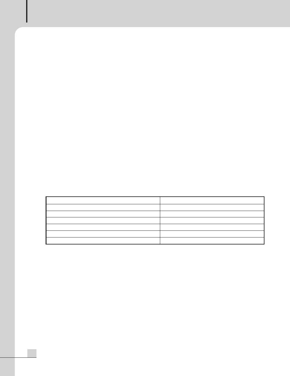
10. REMOTE CONTROL INPUT
By connecting a 15-pin D-SUB connector, it is possible to control speaker zone selection and activate the
chime via wired remote. Connection terminals for the remote are shown below.
NOTE:
Remote controller is used to RM-01.
11. PREAMP OUTPUT
This output connects the unit with an external power amplifier. Inserting a plug into the Preamp Out jack will
disconnect signal to the unit’s power amp, sending the output of the internal mixer to the external amplifier.
12. AMP IN
This input connects an external mixer or preamp with the unit’s power amp. Inserting a plug into the Amp In jack
will disconnect all input signal from the unit’s internal mixer. Only signal from the external source will be heard.
13. LINK IN
This line-level input connects the unit with an external mixer for expanded input channels.
Pin 1: Remote amplifier input signal hot(+)
Pin 8: Remote control 5(Speaker 5)
Pin 2: Remote amplifier input signal cold(–)
Pin 9: Remote control ground
Pin 3: Signal ground
Pin 10: DC +24V
Pin 4: Remote control 1(Speaker 1)
Pin 11: Input Chime
Pin 5: Remote control 2(Speaker 2)
Pin 12: NC
Pin 6: Remote control 3(Speaker 3)
Pin 13: NC
Pin 7: Remote control 4(Speaker 4)
Pin 14, 15: NC