Front panel, Public address amplifier – Inter-M A-120 User Manual
Page 6
4
A-60/120
PUBLIC ADDRESS AMPLIFIER
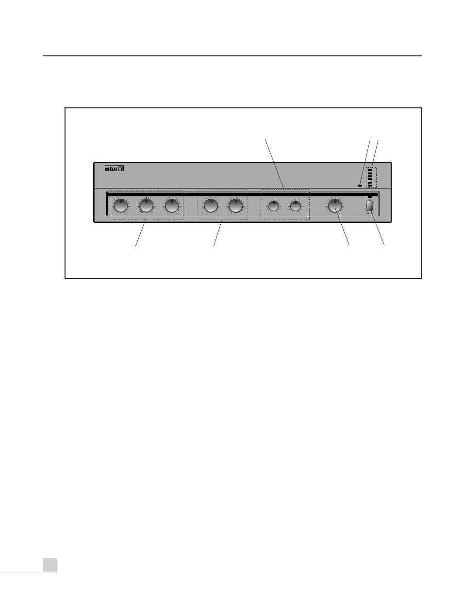
Front Panel
Front Panel
1. BASS AND TREBLE CONTROLS
These knobs provide continuous control of the high and low frequency response, by adding up to 12dB of cut
(decrease) or boost (increase).
2. PROTECTION INDICATOR
This LED indicates the state of the amplifier’s protection circuitry. When the Protection LED is on (illuminated),
the protection circuitry is active, indicating that the unit is not operating normally. This is typically due to
overheating or power limiting. Please check the Input and Output condition of the amplifier.
3. OUTPUT LEVEL DISPLAY
This six-segment LED meter indicates the amplifier’s output level in RMS.
4. MIC VOLUMES 1-3
These knobs provide continuous control of the volume of Mic Inputs 1-3.
5. AUX VOLUME 1-2
These knobs provide continuous control of the volume of Aux Inputs 1 and 2.
6. MASTER VOLUME
This knob provides continuous control of the overall volume of the A-60/120 output.
7. POWER SWITCH
Pressing this switch turns the unit on, as indicated by the Power LED above the switch. Pressing it again turns
the unit off.
PUBLIC ADDRESS AMPLIFIER
A-60
PROT
-14
MIN
MAX
MASTER
MIN
MAX
MIC 2
POWER
MIN
MAX
MIC 1
MIN
MAX
MIC 3
-12dB
+12dB
TREBLE
MIN
MAX
AUX 1
MIN
MAX
AUX 2
-12dB
+12dB
BASS
-10
-7
-3
0
+3
ON
OFF
7
6
1
3
2
5
4