Px-8000 rear panel, Px-8000 – Inter-M PX-8000 User Manual
Page 9
8X8 AUDIO MATRIX SYSTEM
7
PX-8000
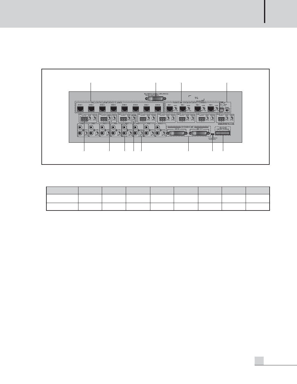
PX-8000 Rear Panel
PX-8000 Rear Panel
1. LM-8000 CONNECTION TERMINAL
A LM-8000 can be connected every output zone.
Ex) RX- of PX-8000 is connected to TX- of LM(RM)-8000 and RX+ of PX-8000 is connected to TX+ of
LM(RM)-8000.
2. 8-CH LUMP OUTPUT TERMINAL
A lump output terminal of 8-CH. Same function as individual output terminal of zone.
3. RM-8000 CONNECTION TERMINAL AND VOLUME
4 units of RM-8000 can be connected.And to adjust input sound by RM-8000.
Its priority is order of RM1 > RM2 > RM3 > RM4. Connection method is same as LM-8000.
4. PAGING MIC CHIME MODE SWITCH AND PHANTOM POWER SWITCH
The Paging MIC is built-in a Phantom Power (DC +24V) in order to support a condenser MIC as well as
general dynamic MIC and is a switch to turn ON/OFF. You can use a dynamic MIC for Off and use a
condenser MIC for On.
Set the mode so that Chime broadcasting is automatically done before or after broadcasting using a DIP Switch.
(Chime increased by 2 tones is broadcast if the upper 2 tones and the upper 4 tones are set to On. Chime
function operates when pressing the TALK button of the paging broadcasting.)
A. SWITCH1 ON : Chime increased by 2 tones for starting is broadcast when pressing the TALK button.
B. SWITCH2 ON : Chime increased by 4 tones for starting is broadcast when pressing the TALK button.
C. SWITCH3 ON : Chime decreased by 4 tones for ending is broadcast when pressing the TALK button.
D. SWITCH1, 2 ON : Same as for SWITCH1 ON.
1
2
3
4
5
6
8
9
10
11
12
7
PIN Number
1
2
3
4
5
6
7
8
Functions
RX-
RX+
TX-
TX+
GND
VCC
AUDIO+
AUDIO-
Color
BLU
BLU/WHT
GRN
GRN/WHT
ORG
ORG/WHT
BRN
BRN/WHT