Inter-M PX-8000 User Manual
Page 10
8X8 AUDIO MATRIX SYSTEM
8
PX-8000
5. ZONE INDIVIDUAL OUTPUT TERMINAL
An output terminal of Balanced Audio.
6. OUTPUT BASS CONTROL VOLUME
Adjusts level of the Balanced Audio output in a low frequency range (100Hz).
7. BGM SOURCE INPUT TERMINAL
An input terminal to input BGM Source.
8. OUTPUT TREBLE CONTROL VOLUME
Adjusts level of the Balanced Audio output in a high frequency range (10kHz).
9. VOLUME TO ADJUST BGM SOURCE INPUT SOUND
Designed to control various input volume as volume to adjust input sound by BGM Source.
10. INTERFACE LINK IN / LINK OUT JACK
A terminal to input/output MAIN BGM, PAGING MIC and data for PX-8000 link.
LINK IN: Connects to LINK OUT of the upper PX-8000.
LINK OUT: Connects to LINK IN of the lower PX-8000.
11. LINK MODE SWITCH [MASTER/SLAVE]
A switch to set the link mode for PX-8000 link
Only the highest PX-8000 for the system link is set to "MASTER" and all the remaining lower PX-8000 are set
to "SLAVE".
12. FIRE ALARM CONTACT [BUILT-IN RECORDING IC AUTOMATIC PLAY]
This is a contact input terminal to emitting automatic emergency broadcasting for emergency in connection
with the fire detector. Broadcasting contents previously recorded in the built-in recording IC are automatically
playbacked in link with the contact.
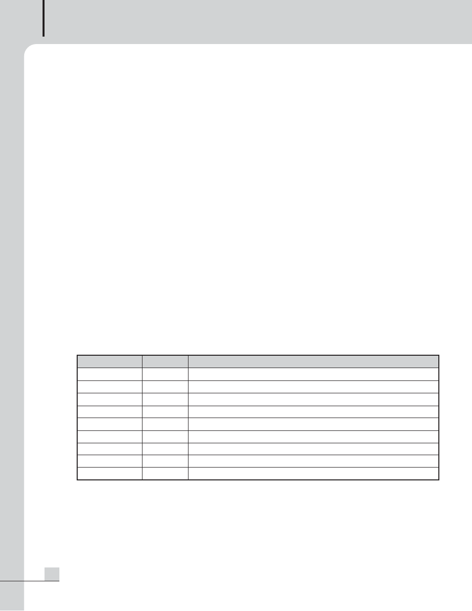
PIN Number
1
2
3
4
5
6
7
8
9
PIN NAME
Functions
Zone 1 CC
Contact input for zone 1
Zone 2 CC
Contact input for zone 2
Zone 3 CC
Contact input for zone 3
Zone 4 CC
Contact input for zone 4
Zone 5 CC
Contact input for zone 5
Zone 6 CC
Contact input for zone 6
Zone 7 CC
Contact input for zone 7
Zone 8 CC
Contact input for zone 8
GND
COMMON GROUND