IDEC SG4 Type 4 Finger & Hand User Manual
Page 4
A Keep the receiver in a steady position and set the emitter until the yellow LED (
SYNC) is OFF.
This condition shows the effective alignment of the first beam (synchronisation beam).
B Rotate the emitter, pivoting on the lower optics axis, until the yellow LED (
LAST) is OFF.
NOTE: Ensure that the green LED (
NORMAL OP.) is steady ON.
C Delimit the area in which the green LED (
) is steady through some micro adjustments - for the first
and then for the second unit - so to have the maximum alignment (4) and then place both units in the
centre of this area.
D Fix the two units firmly using brackets.
Verify that the green LED (
) on the RX unit is ON and beams are not interrupted, then verify that
the red LED turns ON if even one single beam is interrupted SAFE(BREAK)
, condition where an
object has been detected).
This verification shall be made with the special cylindrical “Test Piece” having a size suitable to the
resolution of the device used (refer to paragraph 2.2.6 “Controls after first installation”).
E Switch OFF and ON the device in standard operating mode.
The alignment level is monitored also during device normal operation mode via display (see paragraph
7.2 on the manual inside of the attached CD-ROM).
Once the curtain has been aligned and correctly fastened, the display signal is useful both to check the
alignment and show a change in the environmental conditions (occurrence of dust, light disturbance and
so on) via signal level monitoring.
DIAGNOSTICS FUNCTION
The operator can visualise the operating condition of the light curtains thanks to a one-digit display
positioned on both the RX and TX unit. SG4-B also has four LEDs on the RX unit and two LEDs on the TX
unit.
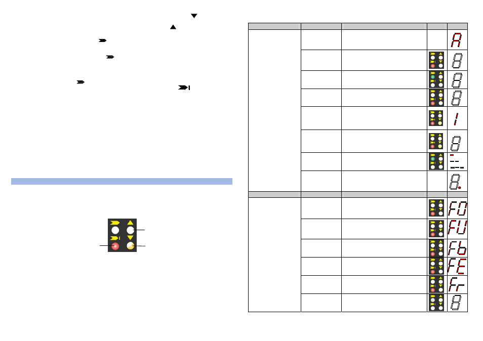
The figure below shows all signalling LEDs modes: OFF, ON and BLINKING.
4
The operator can evaluate the main causes of the system stopping or failure using the 7-segment display
and LEDs used to visualise the functions. For the receiver:
Function
Status
Meaning
LED
DIGIT
Alignment
See section 5
TEST
(red ON)
Light curtain being tested. OSSD status
shall be OFF
Emission
(OSSD ON)
(green ON)
Light curtain working in normal operating
conditions
Interruption
(OSSD OFF)
(red ON)
Light curtain working in safety block
conditions.
Interlock
Beams free
(red ON
yellow ON)
Light curtain in interlock, waiting for
restart. OSSD status must be OFF
Interlock
Beams interrupted
(red ON
yellow ON)
Light curtain in interlock. OSSD status
must be OFF
Signal level
Minimum (1 bar)
Medium (2
bar)
Maximum (3 bar)
Normal operation
EDM enabled
EDM function is selected
Function
Type
Check and repair
LED
DIGIT
OSSD error
(red ON)
Check OSSD connections. Make sure that
they are not in contact with one another or
with the supply cables, then Reset. If the
failure continues contact DATASENSOR
Internal error
(red ON)
Switch OFF and switch ON the power
supply circuit. If the failure continues
contact DATASENSOR
Optical error
(red ON)
Reset. If the failure continues contact
DATASENSOR
EDM error
(red ON)
Check EDM connections and lines. If the
failure continues contact DATASENSOR
Restart selection
error (red ON)
Check the man/auto restart connection. If
the failure continues contact
DATASENSOR
Error status
No power supply
(LEDs OFF)
Check connections and input voltage
value. If the failure continues contact
DATASENSOR
5
LED ON
LED OFF
LED BLINKING