G. diagrams for sidewall venting – HTP EFT-399 User Manual
Page 41
41
LP-387 REV. 6.10.14
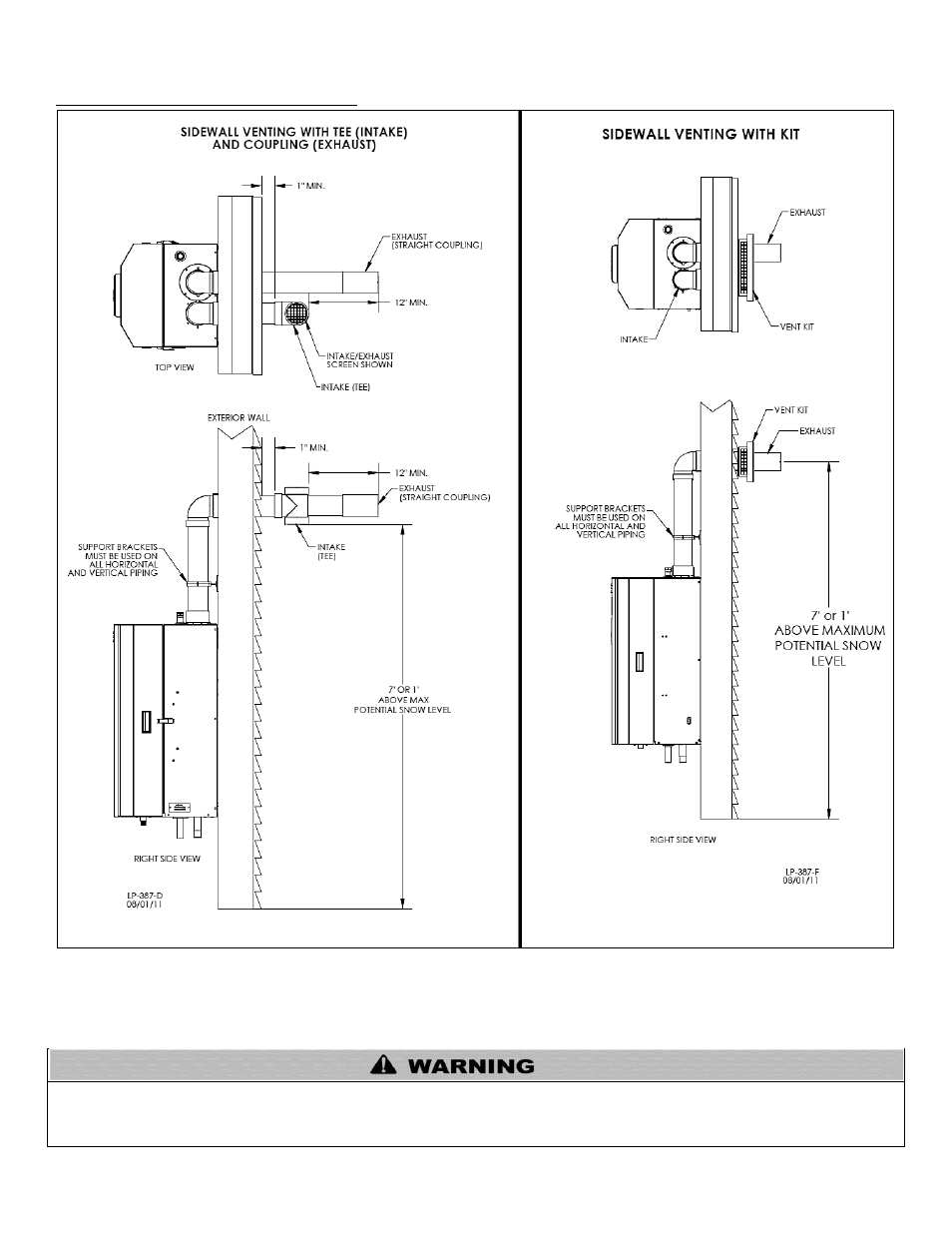
G. DIAGRAMS FOR SIDEWALL VENTING
NOTE:
Vent piping should be 12” over anticipated maximum snow level.
NOTE: Drawing is meant to demonstrate system venting ONLY.
All vent pipes must be glued, properly supported, and the exhaust must be pitched a minimum of ¼” per foot back to the boiler to allow
drainage of condensate. When placing support brackets on vent piping, the first bracket must be within 1 foot of the boiler and the
balance at 4 foot intervals on the vent pipe. Boiler venting must be readily accessible for visual inspection for the first three feet from the
boiler.
Figure 19
– Sidewall Venting with Tee (Intake) and Coupling (Exhaust) (Standard Equipment) and with Optional Kit