Fig. 2, Ybo-r/3, Ybo-r/sci – Hochiki CHQ-AB User Manual
Page 2
2-3-0-568/ISS4/DEC13
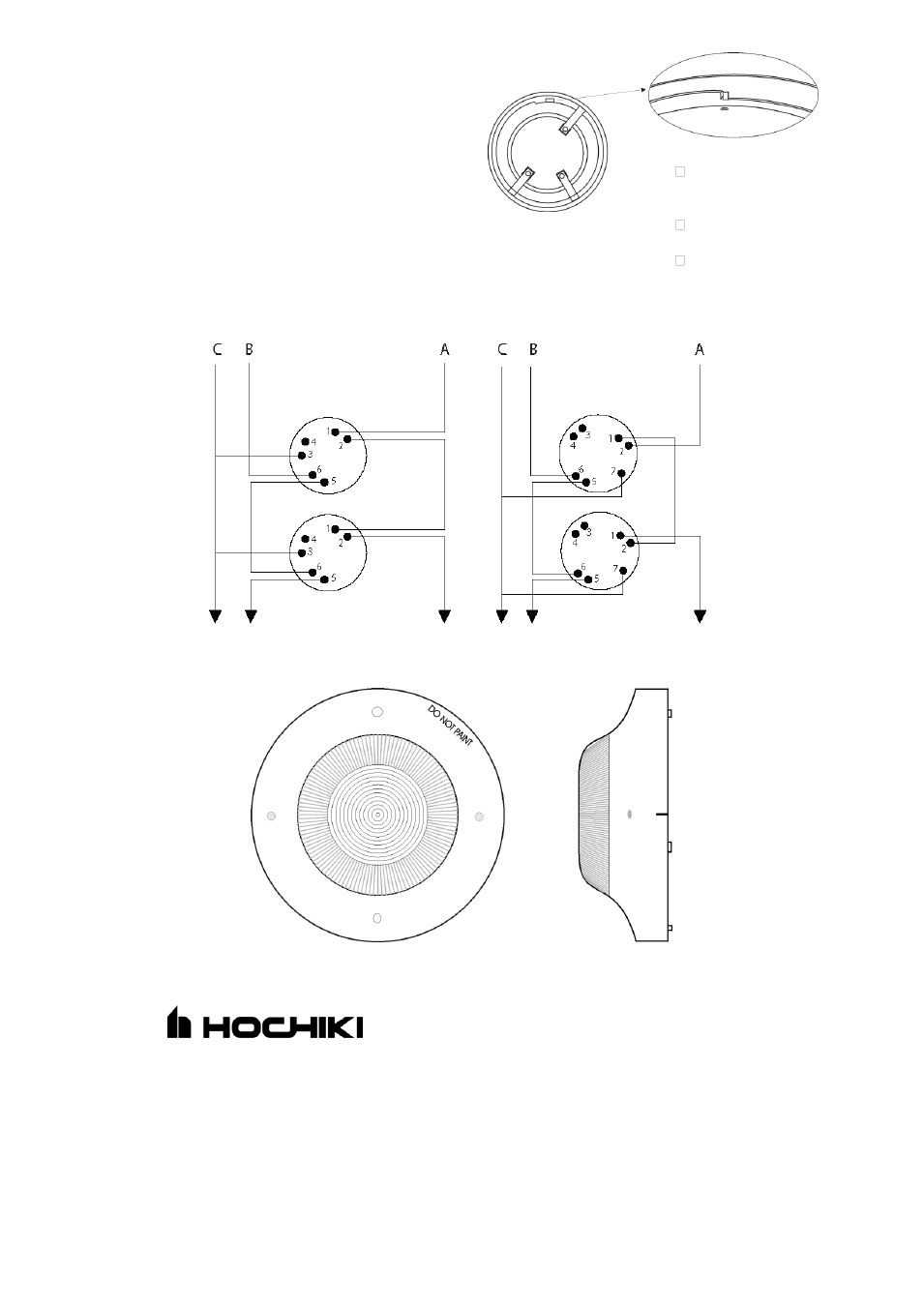
Wiring and Locking Mechanism
The bases used with the beacon should be wired as
shown in Fig 2 below. The CHQ-AB can also be
locked onto the relevant base by removing a plastic
lug on the underside of the beacon, please refer to
Fig 1. The beacon can only then be removed by
using a special Removal Tool (TSC-A100/ALG)
which is available from Hochiki Europe (UK) Ltd.
A: Loop (+) B: Loop (-) C: Cable Screen
Hochiki Europe (UK) Ltd. reserves the right to alter the
specification of its products from time to time without
notice. Although every effort has been made to ensure
the accuracy of the information contained within this
document it is not warranted or represented by Hochiki
Europe (UK) Ltd. to be a complete and up-to-date
description. Please check our web site for the latest
version of this document.
Hochiki Europe (UK) Ltd
Grosvenor Road, Gillingham Business Park,
Gillingham, Kent, ME8 0SA, England
Telephone: +44(0)1634 260133 Facsimile: +44(0)1634 260132
Email: [email protected]
Web: www.hochikieurope.com
Fig 1
Remove tab carefully
using a pair of pliers
NOTE:
Maximum current for
remote indicator is
10mA.
Base fixing centres are
48mm to 74mm
Maximum wire thickness
is 2.5mm
2
/terminal
Fig. 2
Fig 2
YBO-R/3
YBO-R/SCI