Installation: a85 integrated amplifi er, Positioning the unit, Connecting to loudspeakers – Arcam P85 User Manual
Page 4
A85/P85
4
Installation: A85 integrated amplifi er
Positioning the unit
Place your amplifi er on a level, fi rm surface.
Avoid placing the unit in direct sunlight or near sources of heat
or damp.
Ensure adequate ventilation. Do not place the unit in an
enclosed space such as a bookcase or cabinet as both of
these will impede air fl ow through the ventilation slots.
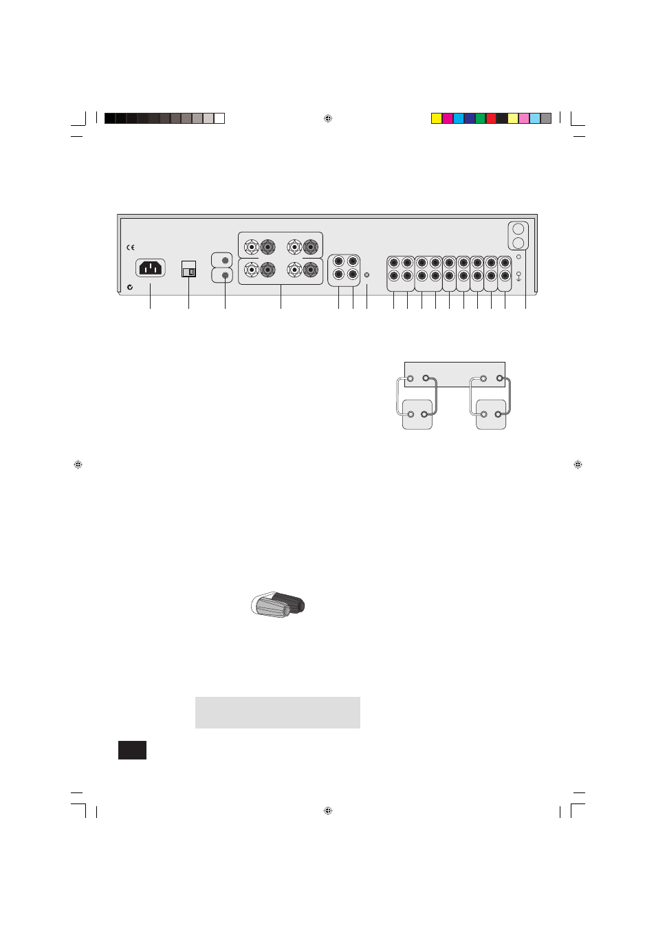
Connecting to loudspeakers
You can connect one or two pairs of loudspeakers to your
amplifi er, provided each pair is rated between 8–16
Ω. If one or
both pairs have an impedance of less than 8
Ω, the combined
load on the amplifi er falls below 4
Ω and could cause an
overload. If so, the overload protection circuit engages and the
amplifi er will not work.
To connect one pair of loudspeakers, use the
SP1
terminals.
SP1 and SP2 terminals
4
Both sets of loudspeaker terminals can be switched off by
pressing the
MUTE
button on the remote control. To switch
SP1
and
SP2
independently, use the front panel switch
7
(see
page 6) or the remote control (see page 9).
Your amplifi er is fi tted with loudspeaker terminals to BFA
(British Federation of Audio) standard specifi cation.
BFA loudspeaker terminals
The terminal will accept spade terminals, bare wires or a
BFA plug. BFA plugs are available from your Arcam dealer. To
connect a bare wire or spade terminal, unscrew the red (or
black) part of the loudspeaker terminal fi rst.
Insert the wire or spade terminal and screw it back up.
CAUTION: Do not over tighten the loudspeaker terminals or
use a wrench, pliers, etc., as this could cause damage to the
terminals which will not be covered under warranty.
Connect the right speaker to the terminals on the back of
your amplifi er marked
R
and the left speaker to the terminals
marked
L
.
Connect your loudspeakers so that the red (positive/+) terminal
on each loudspeaker is connected to the red (positive/+)
terminal on the amplifi er. Your loudspeaker cables may be
marked to show polarity (negative/– and positive/+), if not, then
the positive terminal can usually be identifi ed by a ridge or
coloured marking.
Now connect your loudspeakers’ black (negative/–) terminals to
the black (negative/–) terminals on the amplifi er.
Ensure that no stray strands of inner wires are allowed to touch
another cable or the amplifi er’s casing. This can cause a short
circuit and damage your amplifi er!
Wiring your loudspeakers
L
R
+
–
PHONO
+
–
SP1
SP2
POWER INLET
PRE OUT
PWR IN
6
8 9 bk bl bm bn bo bp
5
4
bq
1
4 – 16 OHMS
L
R
L
R
L
R
VOLTAGE
SELECT
230V
RECORD
OUT
PLAY
IN
TAPE 1
RECORD
OUT
PLAY
IN
VCR/TAPE 2
DVD
AV
TUNER
CD
AUX
INTEGRATED
PRE/PWR
MM
MC
3
2
REMOTE
IN
TRIG
OUT
7
br
Arcam A85 amplifier
R
L
+
–
+
–
Right
speaker
+
–
–
+
Left
speaker
A85/P85 multi.id
03/29/01, 3:34 PM
4