Shaft connections, Instruction manual – Grove Gear Helical-Inline Aluminum (P Series) User Manual
Page 5
Shaft Connections
provide suitable guards in accordance with OSHA standards.
Input and output shaft extension diameter tolerance is +0.000”; -0.001” for shafts up to 1.375” diameter. The fitted component must be machined to ensure
proper fit .
DO NOT drive coupling hub, pinion, sprocket or pulley on the shaft. An endwise blow on the shaft may damage gears and bearings. Coupling hubs,
pinions, sprockets or pulleys must be pushed onto the shaft using a screw jack device fitted into the threaded hole provided in the end of the shaft, see
Table 3 below.
Output Shaft
Input Shaft
Drive Size
Tap Size
Depth
Tap Size
Depth
717
1/4-20
.62
1/4-20
.62
727
5/16-18
.75
1/4-20
.62
747
5/16-18
.75
5/16-18
.75
757
5/16-18
.75
5/16-18
.75
Table 3 - Shaft End threaded Holes - Inches
H7
H6
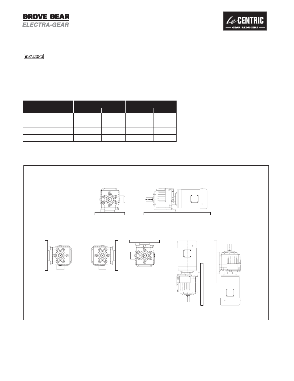
H3 (Standard Position)
V6*
V5
H8
Standard mounting position is H3. All reducers will be filled to this level, unless otherwise specified.
**Not Recommended
Figure 1 - Reducer Mounting Positions
INSTRUCTION MANUAL
™