Grant Part #52203 - Revolution User Manual
Page 2
must find the correct one before proceeding; refer to your vehicle manual for the correct fuse if it is
not number 17. Once you have removed the correct fuse turn the ignition switch to OFF.
NOTICE
- Disconnect the negative battery cable and wait at least
1 full minute
for the circuit to
completely discharge before proceeding. (If your vehicle has any auxiliary batteries or power
supplies disconnect these as well).
CAUTION:
Failure to fully deplete the backup power supply
could result in an accidental deployment and possible injury.
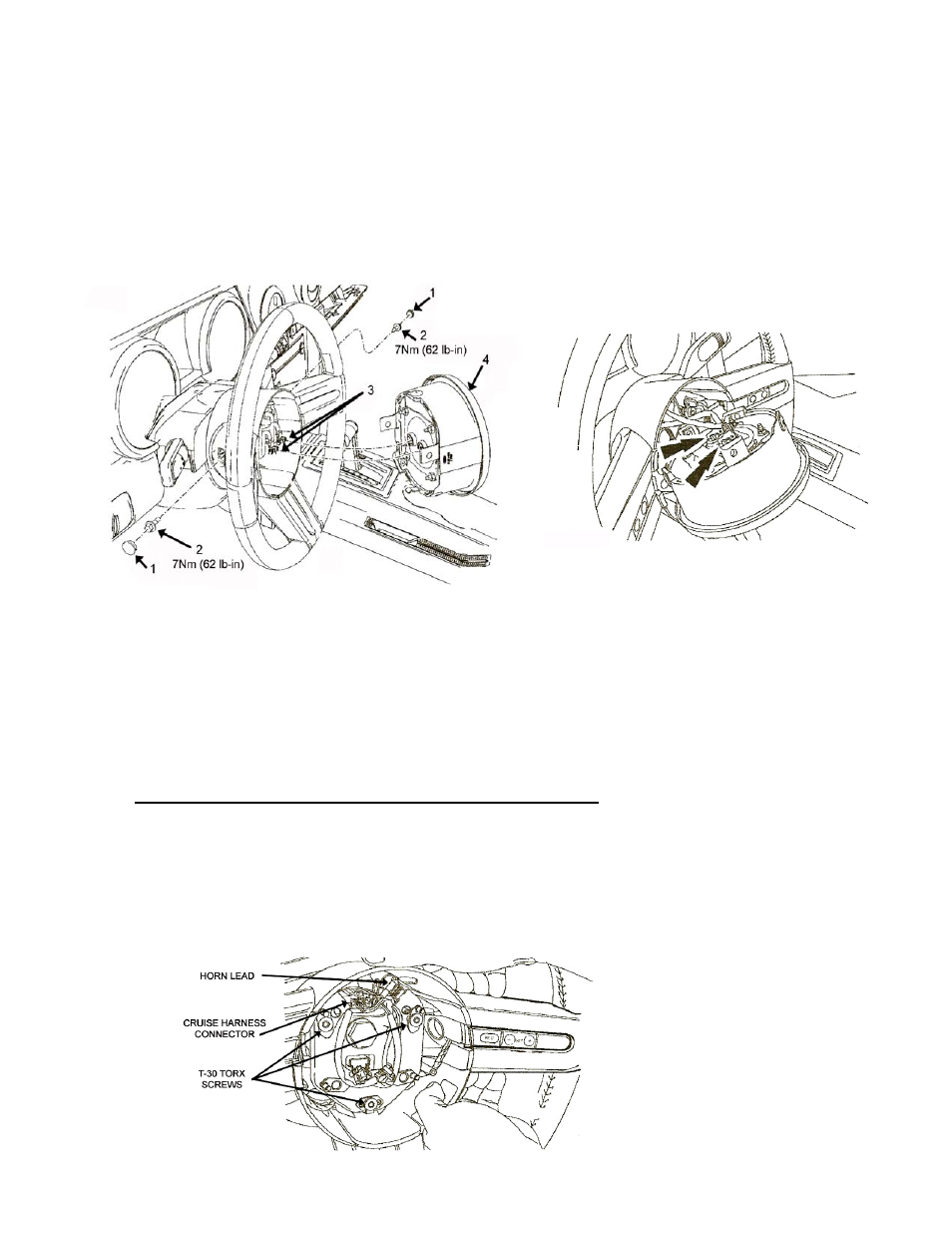
3. Refer to Illustration 1 below and remove the plastic bolt caps (1) from the sides of the steering wheel
by prying out with a small screw driver. Remove the airbag module bolts (2) found underneath these
bolt caps with either an 8mm or 10mm socket.
Illustration 1
Illustration 2
4. Lift and partially remove the airbag module (4) from the steering wheel in order to expose the
electrical connectors (3) on the back side. Take care not to pull on any of the wiring. The
connectors are unique and cannot be reversed when connected so there is no need to mark them.
5. Disconnect the electrical connectors from the airbag module. (Illustration 2)
6. Remove the airbag module from the steering wheel and place the module face up on the floor, seat
or work bench. If you carry the module make sure the trim cover is pointed AWAY from your body.
REMOVING THE STEERING WHEEL FROM THE VEHICLE
1. Remove the three (3) silver spoke trim finish panels by placing your finger tips under the trim at the
outside end where it meets the grip of the wheel and gently pull upward. Once it starts to move it is
easy to remove; just pull straight up.
2. Refer
to Illustration 3 and disconnect the horn lead by pulling off horn switch at the upper right tab.
Disconnect the wheel switch wiring harness at the clockspring column connector.
Do not pull on
the clockspring and do not turn the clockspring now or at any time during installation.
Illustration 3