St50nf-manual-3~4, St50nf – SilverStone ST50NF Manual User Manual
Page 3
ST50NF
The DC loads shall remain within the ranges specified in 2-2 DC Load Requirements and the DC
output voltages also shall remain within the regulation ranges specified in 2-1 Output Regulation
when measured at the load end of the output connectors.
1
2
3
+5V
0.5
18
1
+3.3V
18
0.5
1
+12V
0.5
10
38
-12V
0.5
0.5
0.5
+5VSB
0.1
0.1
0.1
2-2-1. Cross Regulation
The +5Vsb is on whenever the AC power is present.
Note: The measurements should be made by crossing a 47uf/ electrolytic and a 0.1uf ceramic disk
capacitors at each output with measuring bandwidth from DC to 20 mhz. If ambient temperature is
under 20 C or over 30 C, the AC input should be nominal input.
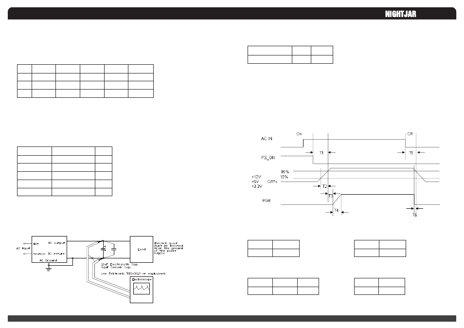
Figure 1. Differential Noise Test Setup
2-3. +5V standby voltage
03
Output Voltage
+5V
+12V
-12V
+3.3V
+5Vsb
Ripple & Noise Max
50
120
120
50
50
Units
Mv
Mv
Mv
Mv
Mv
2-2-1. Cross Regulation
o
o
04
2-5. Total Output Power
Ac Input Voltage
99V~264Vac
MAX
500
Units
Watts
MAX
500
Units
Ms
The power supply outputs shall be enabled with an active-low TTL signal.
When TTL signal is low, the DC outputs are to be enabled.
When TTL signal is high or open circuited, the DC outputs are to be disabled.
Electronic means or a mechanical switch may activate the TTL signal.
After the TTL signal is active high, must wait for 3 seconds before active low again.
2-6. Remote ON/OFF Control
FIGURE 2. Power Sequence
The test environment is 25 C condition
@ nominal input. See1-1
2-8. Power On Time (T1)
MAX.
70
Units
Ms
2-9. Rise Time (T2)
MIN.
100
MAX.
500
Units
Ms
2-10. Power Good Delay Time (T3)
MAX
10
Units
Ms
2-11. Power Good Rise Time (T4)
2-7. Power Sequence
o