Audiovox MMD10 User Manual
Page 15
15
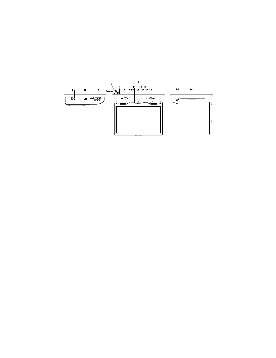
E. Controls, Indicators, and Connectors
1. Unit View (Refer to Figure 6)
Figure 6
1) AV 2 In
2) Headphone Jack
3) FM Modulator Switch
4) Auto/Off/On Dome Light Switch
5) Power and Dome Light Connector
6) AV IN RCA Jacks(red,white,yellow)
7) AV Output RCA Jacks (red,white,yellow)
8) Power Button
9) Reverse Scan Button
10) Stop Button
11) Forward Scan Button
12) Monitor Release Button
13) IR Sensor and IR Transmitter
14) Volume -
15) Picture
16) Volume +
17) Play button
18) Dome Lights
19) Eject button
20) Disc Insertion Slot
See also other documents in the category Audiovox Car speakers:
- AVD300T (30 pages)
- Prestige Detachable Face Stereo Systems (4 pages)
- Rampage ACD28 (20 pages)
- P-57S (12 pages)
- ACC-30 (4 pages)
- CD3720 (15 pages)
- CDC-TO2 (2 pages)
- ACD-27 (16 pages)
- Jensen Phase Linear PCD160U (48 pages)
- MP5620 (26 pages)
- Commander MT XMRVRFM002 (64 pages)
- CDC-FDR (2 pages)
- ACD-13 (16 pages)
- Jensen VM8022 (24 pages)
- AV1410 (76 pages)
- Jensen Phase Linear UMP8015 (59 pages)
- CD CHANGER CONTROLS AND QUARTZ CLOCK AAAAAV-427V-427V-427V-427V-427 (12 pages)
- Prestige P942WESP (12 pages)
- Jensen CD3720XM (20 pages)
- PCR2500 (24 pages)
- MM850 (16 pages)
- CD4720 (16 pages)
- Jensen MPA6611X (20 pages)
- PAV-8000D (30 pages)
- AVD400TA (24 pages)
- Prestige P950WESP (5 pages)
- Jensen Phase Linear UMP400 (54 pages)
- PAV-7 (10 pages)
- LCM1331FD (15 pages)
- Jensen JPA1150M (19 pages)
- Jensen MP6512i (30 pages)
- BA200 (6 pages)
- P-955 (18 pages)
- Prestige Car Stereo System (4 pages)
- Jensen VM9411 (110 pages)
- P-15 (8 pages)
- Prestige P959ESP (20 pages)
- AVD400T (12 pages)
- SW-50 (4 pages)
- US240 (5 pages)
- AVT-597 (21 pages)
- P-945 (16 pages)
- MMSV58 (10 pages)
- P-942 (12 pages)