Operating manual – Robinair 15120A_15121A User Manual
Page 4
Operating Manual
3
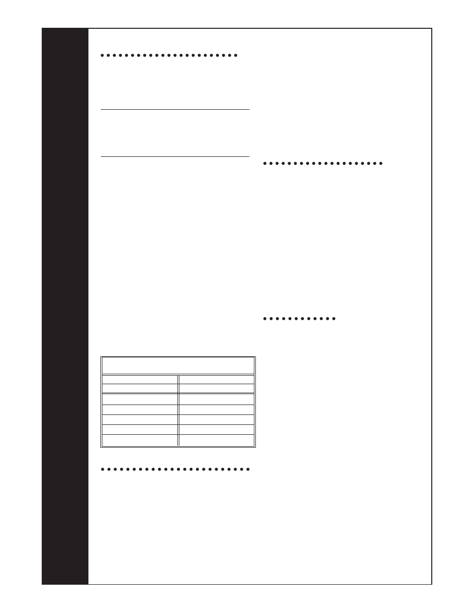
15121A Wiring Instructions
The CoolTech vacuum pump features dual
voltage ranges. Before operating the pump,
read and follow these rewiring instructions (if
necessary) to be certain your pump is wired for
the appropriate voltage.
CAUTION: To prevent personal injury,
unplug the unit before beginning service
work. Incorrect use or connections can
cause electrical shock. Only qualified
personnel should perform service work.
The CoolTech vacuum pump is factory wired for
a high voltage of 220 volts. To wire the switch
for a low voltage range of 110 volts to 127 volts,
follow these steps:
1. Disconnect unit from the AC power source.
2. Loosen the screws on the plate at the rear
of the motor, and carefully move the plate
aside to clear the opening.
3. Disconnect the leads, and reconnect for low
voltage according to the following chart.
(High voltage connections are also shown,
in case you want to rewire at some time.)
4. Verify all connections are secure, and there
are no short circuits. Verify the grounding
connector is correctly connected.
5. Reinstall the plate on the rear of motor with
the screws that were loosened in Step 2.
6. Use a continuity tester to check for short
circuits before reconnecting the unit to the
AC power source.
To use the gas ballast feature
Moisture from the A/C-R system, carried into the
pump as a vapor, tends to condense into a liquid
and combine with the vacuum pump oil. When
moisture contaminates pump oil, it reduces the
pump’s ability to reach its ultimate deep vacuum.
The gas ballast valve purges a small amount
of atmospheric air through the exhaust
chamber. This extra volume of air mixes with
the vapor from the refrigerant system to prevent
condensation and to help exhaust moisture in
the form of vapor from the pump.
To use the gas ballast, start the pump and open
the gas ballast valve. The valve is located beside
the handle, opposite the inlet fitting. When the
system has reached approximately 1000–3000
microns, close the gas ballast valve to allow the
pump to pull down to its ultimate vacuum level.
The gas ballast valve may be opened or closed
at any time during pump operation. It is fully open
at two turns counterclockwise. Note: Robinair
recommends the use of a thermistor vacuum
gauge to most accurately measure vacuum levels.
To shut down the pump
To help prolong pump life and promote easy
starting, follow these procedures for shutdown:
1. Close the manifold valve between the pump
and the system.
2. Turn the Iso-Valve to the CLOSED position.
3. Remove the hose from the pump inlet.
4. Turn the pump power switch to OFF, then
OPEN the Iso-Valve for a few seconds to
relieve any vacuum inside the pump.
5. Cap the inlet port to prevent any contamination
or loose particles from entering the port.
To maintain your high
vacuum pump
For maximum performance, Robinair recommends
changing vacuum pump oil after each use.
Vacuum pump oil
The condition and type of oil used in any high
vacuum pump are extremely important in
determining the ultimate attainable vacuum. Robinair
recommends the use of our Premium High Vacuum
Pump Oil. This oil has been specifically blended
to maintain maximum viscosity at normal running
temperatures and to improve cold weather starts.
Robinair Premium High Vacuum Pump Oil is
available in convenient pint, quart, or gallon
containers. Order by part number:
13201 — Pint (shipped 12 pints per case)
13203 — Quart (shipped 12 quarts per case)
13204 — Gallon (shipped 4 gallons per case)
Oil change procedure
1. Run the pump until warm.
2. Remove the OIL DRAIN cap. Drain
contaminated oil into a suitable container and
dispose according to local regulations.
Oil can be forced from the pump by opening
the inlet and partially blocking the exhaust
with a cloth while the pump is running. Do not
operate the pump for more than 20 seconds
using this method.
EMERSON MOTOR
ELECTRICAL CONNECTION TABLE
115V
220V
WIRE
TERMINAL No.
WHITE
4
BLACK
2
RED
5
BROWN
3
LINE
1 & 4
WIRE
TERMINAL No.
WHITE
3
BLACK
3
RED
5
BROWN
6
LINE
1 & 4