Typical duct installation, Warning, Table of equivalent duct length – Reversomatic PWS 100L User Manual
Page 2
790 Rowntree Dairy Road, Woodbridge ON, Canada L4L 5V3
Tel: 905-851-6701 Fax: 905-851-8376 [email protected]
w w w . r e v e r s o m a t i c . c o m
1. These units are not to be used to exhaust hazardous or explosive gases.
2. To avoid damage to motor and impeller, keep construction materials such as dry wall spray,
construction dust, construction debris, etc. off power units and ducts leading to units.
CAUTION:
Minimum
120 cfm at:
0.2” w.g.
0.4” w.g.
0.6” w.g.
0.8” w.g.
Maximum Equivalent
Duct Length
50 Feet
75 Feet
100 Feet
125 Feet
45’ + 1
70’ + 1
95’ + 1
120’ + 1
Maximum Duct Length + Number of Elbows
40’ + 2
65’ + 2
90’ + 2
115’ + 2
35’ + 3
60’ + 3
85’ + 3
110’ + 3
30’ + 4
55’ + 4
80’ + 4
105’ + 4
25’ + 5
50’ + 5
75’ + 5
100’ + 5
TABLE OF EQUIVALENT DUCT LENGTH
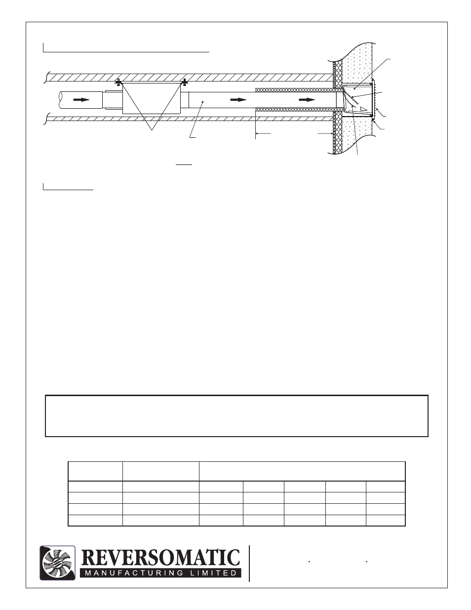
SLOPE
NOTE: USE AS FEW ELBOWS AS POSSIBLE
FAN
INSULATION -
Minimum 5 Feet
(1” Thick)
Rigid Duct Only
Rubber Isolator
BAFFLE
GRILLE
CAULKING
LEAK - PROOF
WALLBOX
NEOPRENE
BACKDRAFT
DAMPER
- 3 SIDES ONLY, NOT ON
BOTTOM (IF CAULKING
ALL 4 SIDES, MUST HAVE
DRAINING HOLES.)
TYPICAL DUCT INSTALLATION
WARNING
TO REDUCE THE RISK OF FIRE, ELECTRIC SHOCK OR INJURY, PLEASE OBSERVE THE FOLLOWING:
1. Installation of these units and the corresponding electrical wiring must be done by a qualified person and be in
accordance with all municipal and national codes and standards, including those related to fire rated construction.
2. Use this units only for intended applications and in the manner indicated by the manufacturer. If you have any
questions please contact the manufacturer at the address or telephone number listed below.
3. Before wiring, servicing or cleaning the units, switch power off at the service panel and lock it. If service panel is
unlocked others could turn the power on unexpectedly and cause fatal electric shock to the installer or service person.
4. When cutting or drilling into wall or ceiling, make sure that you do not damage electrical wiring and other hidden utilities.
5. Always vent units to the outdoors, NOT into unventilated spaces such as garages, attics, crawl spaces, etc.
6. It is recommended that a Lint Trap be installed. Then the location of the Booster Fan can be 15’ to 20’ (10 linear feet)
from the dryer.
7. The Booster Fan blade must be checked at least twice annually for lint accumulation.
8. All Fans should have backdraft damper at outlet. Fans with pressure sensing device must have wall-box equipped with
backdraft damper as per drawing.