Reversomatic RI 150 PS, RI 200 PS, RI 250 PS User Manual
Fans with pressure sensors, Ri-ps fan series tld200-ps series pws-ps series, Installation instructions
790 Rowntree Dairy Road, Woodbridge ON, Canada L4L 5V3
Tel: 905-851-6701 Fax: 905-851-8376 [email protected]
w w w . r e v e r s o m a t i c . c o m
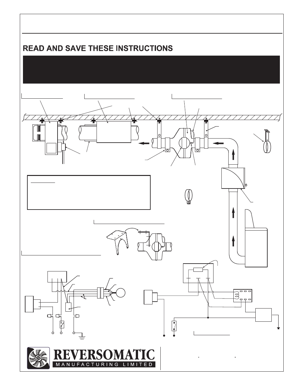
FANS WITH PRESSURE SENSORS
INSTALLATION INSTRUCTIONS
OPTIONAL MOUNTING BRACKET
RI-PS FAN SERIES
TLD200-PS SERIES
PWS-PS SERIES
DRYER
Rubber Isolator
Suspension
Bracket
(Optional)
LINT TRAP
IMPORTANT:
ALL FANS EQUIPPED WITH PRESSURE SENSOR MUST
BE INSTALLED WITH SENSOR MOUNTED VERTICALLY
OR HORIZONTALLY. NEVER INSTALL PRESSURE SENSOR
BARB POINTING DOWNWARD.
Mounting Clamps
(Optional)
Pressure
Sensor
Barb
(Never Pointing
Downward)
120 V AC
Pressure
Sensor
Mounting
Clamps
(Optional)
> use for rigid duct,
complete with foam
rubber isolator.
Tubing
joel tantay 5.19.09
PWS-PS Series
NC
NO
C
RELAY
(10 Amp.)
NC
NO
C
FAN
1
2
3
LOAD
BLACK
WHITE
RED
NO
C
T I M E R
120V AC / 60HZ
POWER SUPPLY
WHITE
RED
BLACK
MAX. LOAD
1.0 Amp.
600 Sec. “ON”
60 Sec. “OFF”
Pressure
Sensor
BLACK
Wall
Switch
TLD200-PS & RI-PS SERIES
Typical wiring Diagram
TIMER
GREEN
BLUE
MOTOR
120 V AC
SW
RED
WHITE
LOAD
WHITE
BLACK
BLACK
BROWN
BLACK
CAPACITOR
BLACK
C
NO
PRESSURE
SENSOR
TO AVOID THE RISK OF FIRE, ELECTRIC SHOCK OR INJURY,
TURN POWER OFF AT SERVICE PANEL BEFORE INSTALLATION
OR CLEANING OR SERVICING THIS UNIT.
CAUTION: