9060 cascade low voltage controller - installation, I/o signal locations – Ransburg 9060 LV Auto Cascade 80120-XXX User Manual
Page 32
9060 Cascade Low Voltage Controller - Installation
27
CP-13-02.2
3. Route the selected shielded cable through
the standard I/O connector and secure it to
the connector as described in “I/O Connec-
tions” in the “Installation” section of this
manual so that the shield of the cable is
connected to the chassis of the enclosure.
Ensure that enough wire length is available
to allow for proper wiring of all of the I/O
signals.
4. Connect the conductors to the respective
remote I/O signal locations. Screw down
the terminal block screws to secure the
conductors in place. The I/O Signal Loca-
tions table contains the complete list of all I/
O, ground, and 24VDC supply locations as
well as their normal voltage/current values.
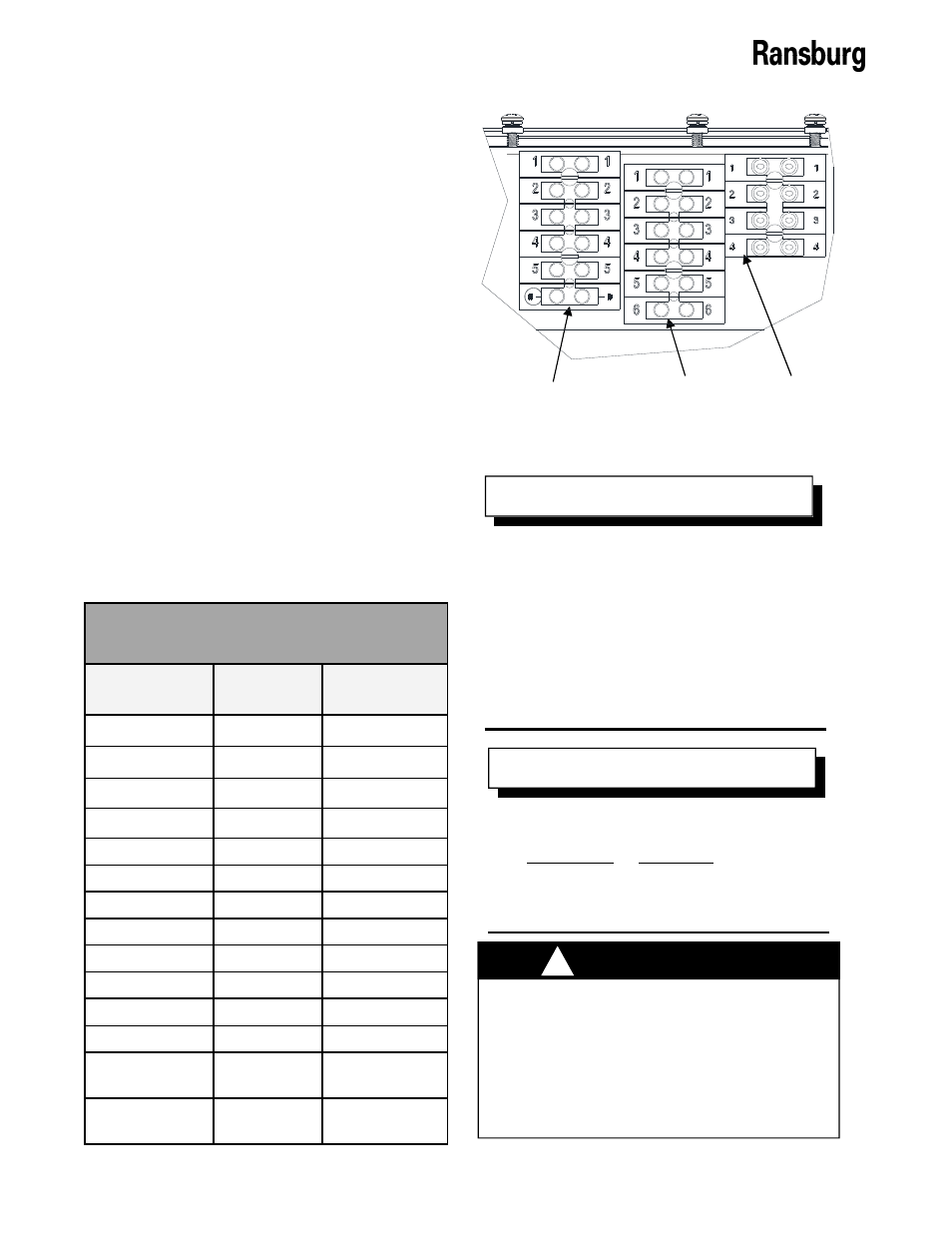
The locations of the I/O terminal blocks are
shown in Figure 16.
I/O Signal Locations
Signal
Terminal
Block
Local/Remote
2TB-4
Tripleset 1 (TS1)
2TB-2
Tripleset 0 (TS0)
3TB-1
Reset
2TB-3
HV On
4TB-3
Relay Common
4TB-2
Fault
4TB-1
24 VDC
3TB-6, 4TB-4
Trigger
2TB-5
Analog Current
3TB-2
Analog Voltage
3TB-3
Analog Common
3TB-4
Analog Feedback
Current
3TB-5
Ground
2TB-6, Ground
Lug
Normal Value
24VDC
24VDC
24VDC
24VDC
24VDC or GND
24VDC or GND
24VDC or GND
24VDC or GND
24VDC or GND
0-20mA
0-10V
Ground (0V)
0-200mA
Ground (0V)
Figure 16: I/O Terminal Block Locations
After securing the conductors to the ter-
minal blocks positions, it is best to per-
form a continuity test between the termi-
nal block screw and the opposite end of
the shielded cable for each conductor to
ensure a good connection has been made
with each conductor. Also a 2 finger pull
test should be done. Pull on each con-
ductor with 2 fingers to ensure it is tight.
N O T E
All of the digital inputs, including the
trigger signal, MUST be configured as ei-
ther all sourcing or all sinking. The trigger
signal is configured through the local/
remote trigger protection board jumper
settings.
N O T E
DO NOT use a sourcing signal with the
9060 jumpers set for sinking inputs or vice
versa. Sourcing and sinking inputs has
different current flow paths. Using the
wrong settings for the wrong type input
can have unexpected behavior and/or
cause damage to the input circuits.
!
W A R N I N G
5. Determine whether the digital signals will
be configured as sinking (grounding input)
or sourcing (powering input).
TB2
TB3
TB4