Needle / electrode, Ransburg, Vector solo 65kv applicator - maintenance – Ransburg Vector Solo 65KV 79965 Solventborne RS70-AS User Manual
Page 29: Reinstall, Removal, Cleaning and inspection
Vector Solo 65kV Applicator - Maintenance
25
AH-08-02.6
Reinstall
1. Check the electrode tightness on the needle
shaft. If it is loose, tighten it (refer to "Needle/
Electrode" in the "Maintenance" section).
2. With the applicator trigger actuated, place the
fluid nozzle over the needle/electrode and screw
it into the barrel by hand.
3. Tighten it using the Special Multi-Purpose
Wrench 79854-00 with 3/8" square. Torque to 40-
45 lbs. - in. (4.5 - 5.1 Nm). An alternate method (if
no torque wrench is available) is to hand tighten,
then tighten an additional 1/16 turn in the clockwise
direction.
4. Install the air cap and retaining ring onto the
applicator.
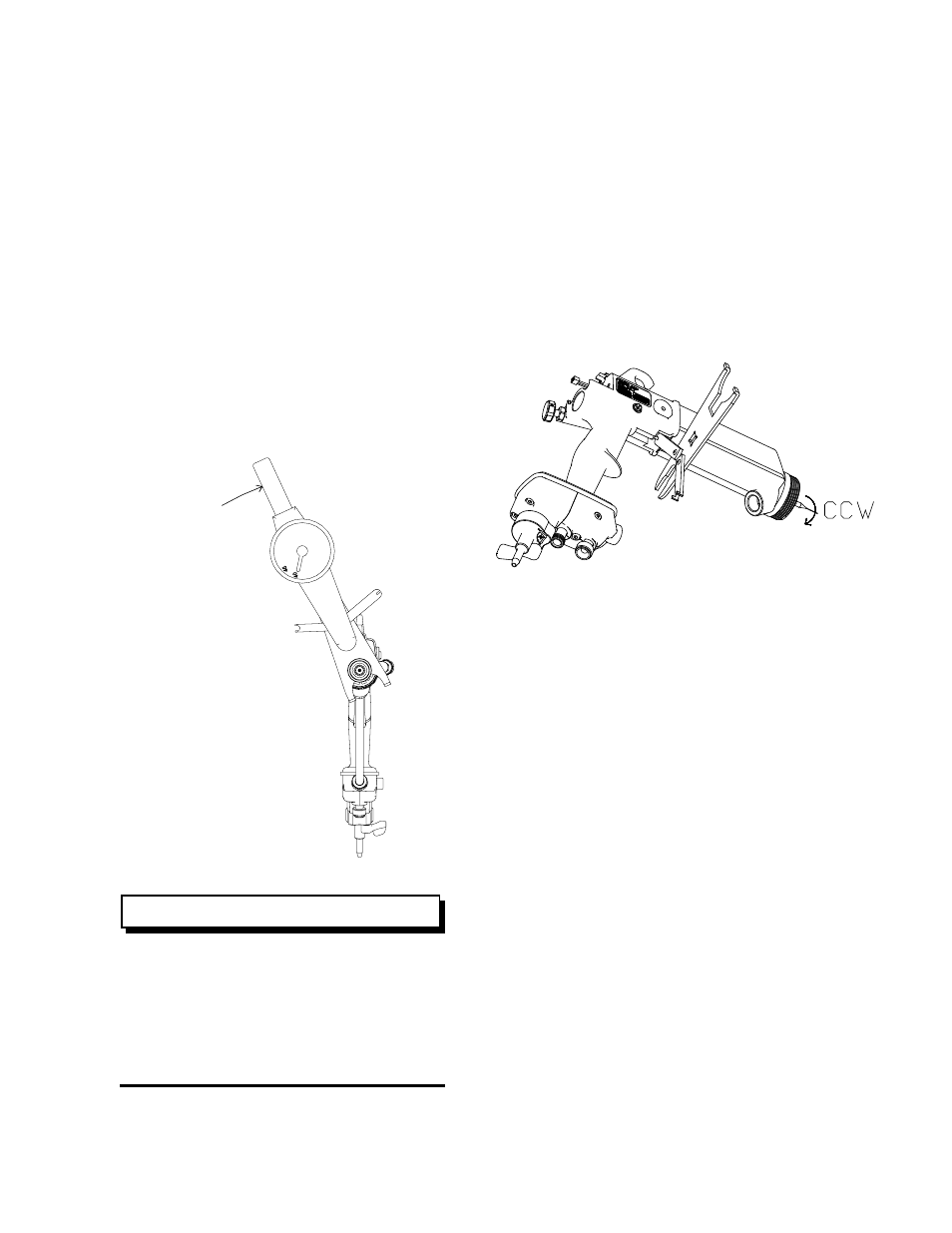
Figure 21: Reinstalling Fluid Nozzle
DO NOT under-tighten the fluid nozzle
as fluid can leak into the air passages.
DO NOT over-tighten the fluid nozzle
into the barrel. Doing so could damage
or break the fluid nozzle or damage the
thread of the barrel.
NEEDLE / ELECTRODE
Removal
1. Remove the air cap and fluid nozzle from the
applicator assembly.
2. Secure the needle shaft at the rear of the barrel
with the Special Wrench 79854-00 and unscrew
the needle/electrode from the needle shaft.
Cleaning and Inspection
1. Use a suitable solvent to clean the needle/
electrode.
2. Examine the needle/electrode for damage or
wear. Pay special attention to the area where
the wire electrode extends from the main body.
This is a sealing surface that seats inside the fluid
nozzle. If there are signs of wear in this area,
both the needle/electrode and fluid nozzle must
be replaced.
3. An electrical check of the needle/electrode must
be done prior to reinstalling it into the applicator
assembly (refer to "Needle/Electrode Resistance
Testing" in the "Maintenance" section).
Reinstall
1. Secure the needle shaft at the rear of the barrel
and screw the needle/electrode into place by hand.
2. Reinstall the fluid nozzle and air cap onto the
barrel.
Figure 22: Electrode Removal
C W
3 5 -4 0
L B S -I N
3 . 9 -4 . 5 N M
NOTE
Ransburg