King Kooker Cast Cooker User Manual
Page 16
High Pressure units with snap on legs
Assembly Instructions
required tools: Adjustable Wrench
Parts List:
(1) Cooker Frame
(1,2 or 3) Castings/Air Shutters
(1) LP Hose/Regulator
(4) Legs
(1) Windguard Shield (if provided)
(1,2 or 3) Deep Fry Thermometers
For Double and Triple Burner Units Only:
(1) Manifold Assembly
(2) Manifold Support Brackets
- (2) Long “Bent” Brackets
- (2) Short Brackets
- (8) Bolts, Lock Washers and Nuts
(1) Storage Locking Bracket, Bolt, Lockwasher and Nut
1)
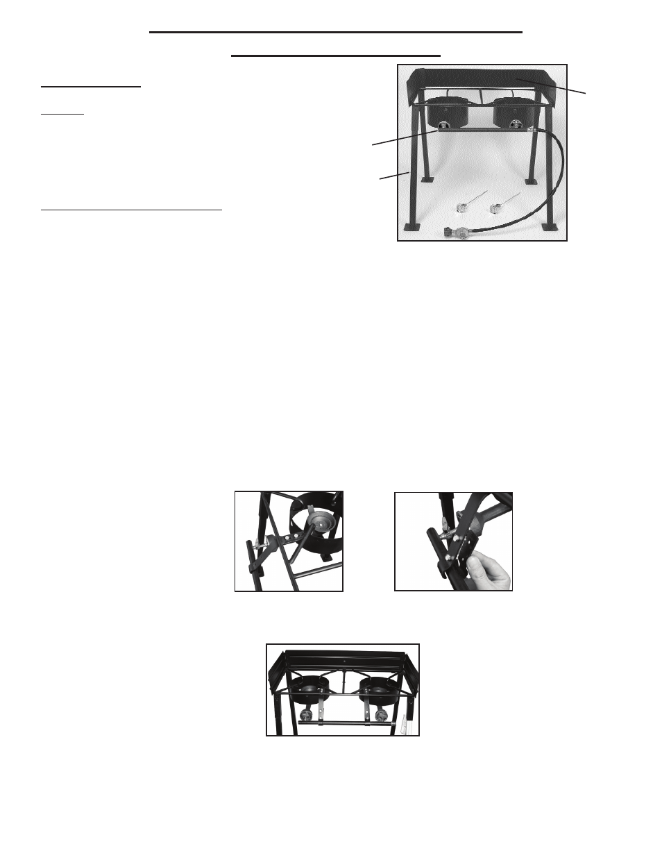
Review the contents in your package. Make sure all listed components for your model are included. You will
either have purchased a single, double or triple burner unit. Pictured above is a double burner unit.
2)
Go to pg. 9 for casting installation instructions.
3)
Install the four legs into the top frame as pictured above. Snap in leg bolts through the receiving holes on the
frame. Make sure the leg bolts pop completely out and legs are securely locked in position.
4) To attach windguard shield to the top frame (if applicable), align the windguard shield to top frame as per
above diagram. Slide windguard into receiving U Clips welded to the cooker frame.
5)
For double and triple burner units only - Installation of Manifold and Support Brackets
a. Locate the manifold assembly. Align the male swivel end fittings on the manifold to the venturi tubes on the
castings. Hand tighten the male swivel fittings into the castings. Once tightened, use an adjustable wrench to
tighten the swivel fittings an additional 1 to 1 1/2 turns.
b. Locate the manifold support brackets - (2 long “bent” brackets and 2 short brackets.) Align the two holes
of one long “bent” bracket to the two holes on one of the pre-welded steel tabs (located between the cooker
frame and windshroud.) The long “bent” bracket should be located underneath the steel tab. The curved end of
the long “bent” bracket should be located above the manifold. Wrench tighten with supplied bolts, lockwashers
and nuts (see below Figure 2).
c. Align the two holes on the short and long support brackets (curved ends of each piece should wrap
around manifold.) Wrench tighten with supplied bolts, lock washers and nuts (see above Figure 3).
d. Repeat the above procedure for the second support bracket. See below Figure 4 for picture of properly
installed manifold support brackets.
6)
Locate the hose/regulator. For single burner units reference Figure 1, pg. 10 for proper hose assembly. For
double and triple burner units, tighten the 3/8 female flare swivel ending of the hose and regulator onto the
manifold as pictured in Figure1 above, with a torque wrench, up to a torque of 95 to 105 lb./inch. Alternatively,
hand tighten securely and then, using a wrench, tighten an additional 1 to 1 1/2 turns.
7)
Go to the use and care section of this manual for further instructions. Refer to #8, page 17 for storage
information (double and triple burner units only.)
Leg
Windguard
Manifold Assembly
Figure 1
Figure 2
Figure 3
16
*Model May
Vary From
Picture
Figure 4