Cs8t assembly instructions, Required tools, Tools required – King Kooker Cast Cooker User Manual
Page 12
12
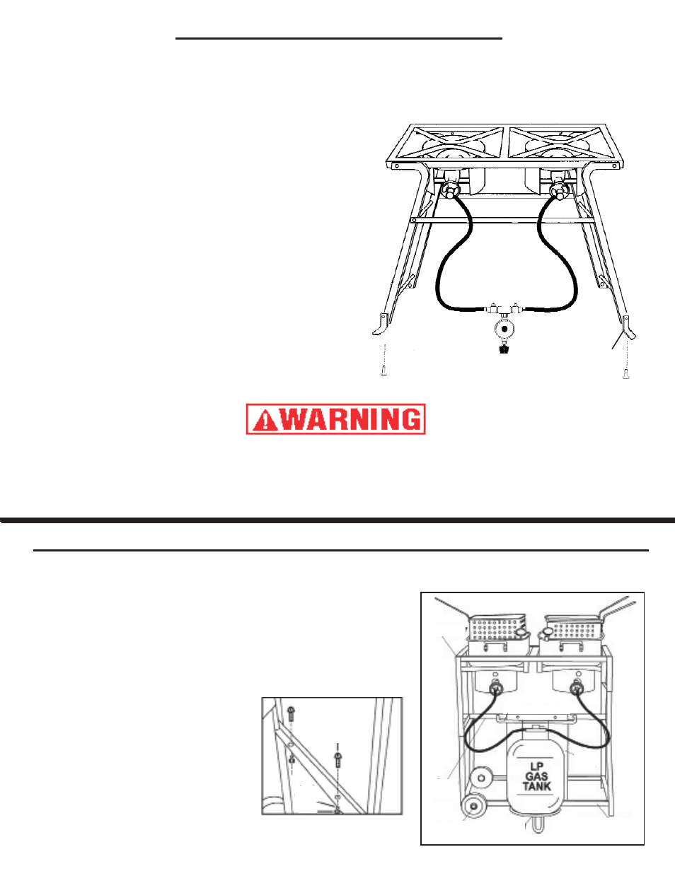
cs8t Assembly InstructIons
reQuIred tools:
AdjustAble WrencH
1. This cooker has four legs with crossbars and two stabilizer bars.
2. Flip the legs into the standing position.
3. Hook each stabilizer bar over the crossbar on the leg
opposite it. The hook on the end of the bar must be pressed
down around the crossbar so that the leg is locked into
position. Always recheck that both hooks are in place before
lighting the cooker or placing cooking equipment on top of
the cooker.
4. Attach a foot extension to each of the four legs. Place the
hole on one of the foot extensions on the outside of the hole
at the bottom of a leg.
5. Place a bolt through the holes on the leg and foot extension
and secure with a nut from the bolt package.
6. Follow the same procedure to attach a foot extension to
each of the remaining three legs.
7. Refer to Figure 4, pg. 11 for hose assembly instructions.
8. Go to the use and care section of this manual for further
instructions.
Foot Extensions
FAIlure to InstAll Foot extensIons or locK stAbIlIzer bArs onto crossbArs
cAn IncreAse tHe rIsK oF tHe unIt tIPPInG. Foot extensIons And stAbIlIzer
bArs must be AttAcHed securely As Per tHe AboVe InstructIons beFore
oPerAtInG tHe cooKer!
KKdFF30t / 8005 / 82-82tKd Assembly InstructIons
tools reQuIred:
AdjustAble WrencH
1. Place top half of unit on bottom half of unit as pictured.
2. Insert four bolts through holes in top and bottom of unit.
Wrench tighten with supplied lock washers and nuts.
3. Attach each wheel to the bottom half of the unit as pictured
using the supplied axels, lock washers and nuts.
4. Attach the cylinder heat plate onto the crossbar as pictured
using two bolts. Wrench tighten with supplied lock washers and nuts.
5. Insert threaded ends of cylinder collar
into crossbar as pictured.
Wrench tighten with supplied lock
washers and nuts.
6. Attach the tank ring to the bottom half of
the unit as per diagram using the U clips
which are welded to the outside of the
frame.
7. Refer to Figure 4, page 11 for hose
assembly instructions.
8. Go to the use and care section of this
manual for further instructions.
1/4 x 1”
Bolt
Lock
Washer
Nut
Top Half
Cylinder Collar
Cross
Bar
Heat
Plate
Wheel/Axle
Tank
Ring
Bottom Half