Kf series, General pump – General Pump KF Repair Manual User Manual
Page 8
GENERAL PUMP
A member of the Interpump Group
KF SERIES
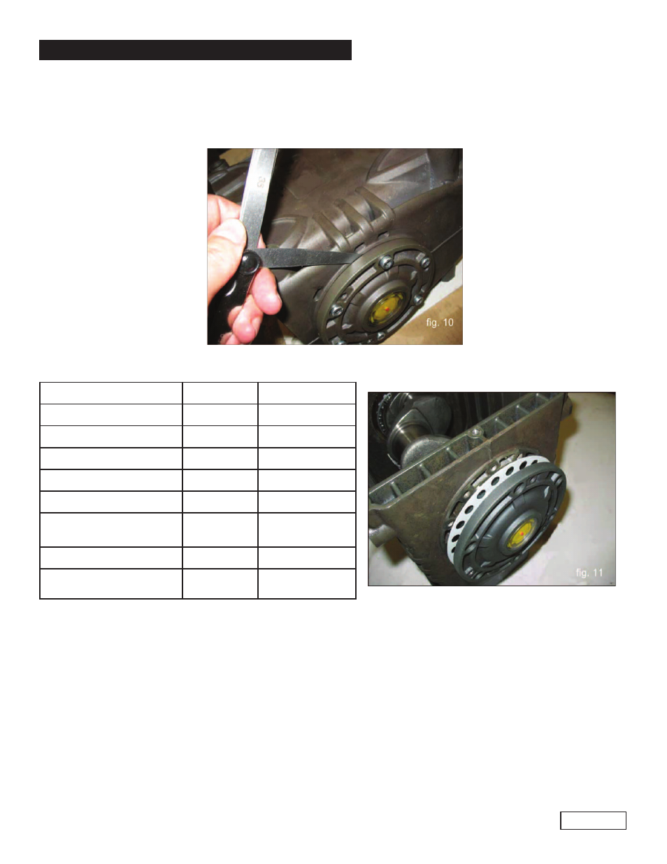
B) Fit the PTO side flange to the crankcase paying great attention to the seal lip as indicated in paragraph
2.1.2., section C.
C) Position the flange on the sight glass side as indicated in paragraph 2.1.
D) 2 using a thickness gauge (see fig. 10).
Page 8
Ref 300912 Rev.A
12-12
Determine the shim pack as indicated in the table below:
Measurement
Shim Type
No. of Pieces
From: 0.05 to: 0.10
/
/
From: 0.11 to: 0.20
0.1
1
From: 0.21 to: 0.30
0.1
2
From: 0.31 to: 0.35
0.25
1
From: 0.36 to: 0.45
0.35
1
From: 0.46 to: 0.55
0.35
0.10
1
1
From 0.56 to: 0.60
0.25
2
From 0.61 to: 0.70
0.35
0.25
1
1
E) Insert the shims of the cover on the sight glass side (see fig. 11), fixing it to the crankcase using the
appropriate screws, and verifying that the stall torque is between 3-5 ft. lbs. (4-7 Nm).
F) If the torque value is correct, connect the rods to the crankshaft; otherwise, redefine the shims again
repeating the operations from point C.
2.2 Fluid End Repair
2.2.1 Disassembly of the head - valve units
Service operations are limited to valve inspection or replacement if needed
To extract the valve units proceed as follows: