General Technologies CT8027 Professional Automotive Digital Multimeter User Manual
Page 3
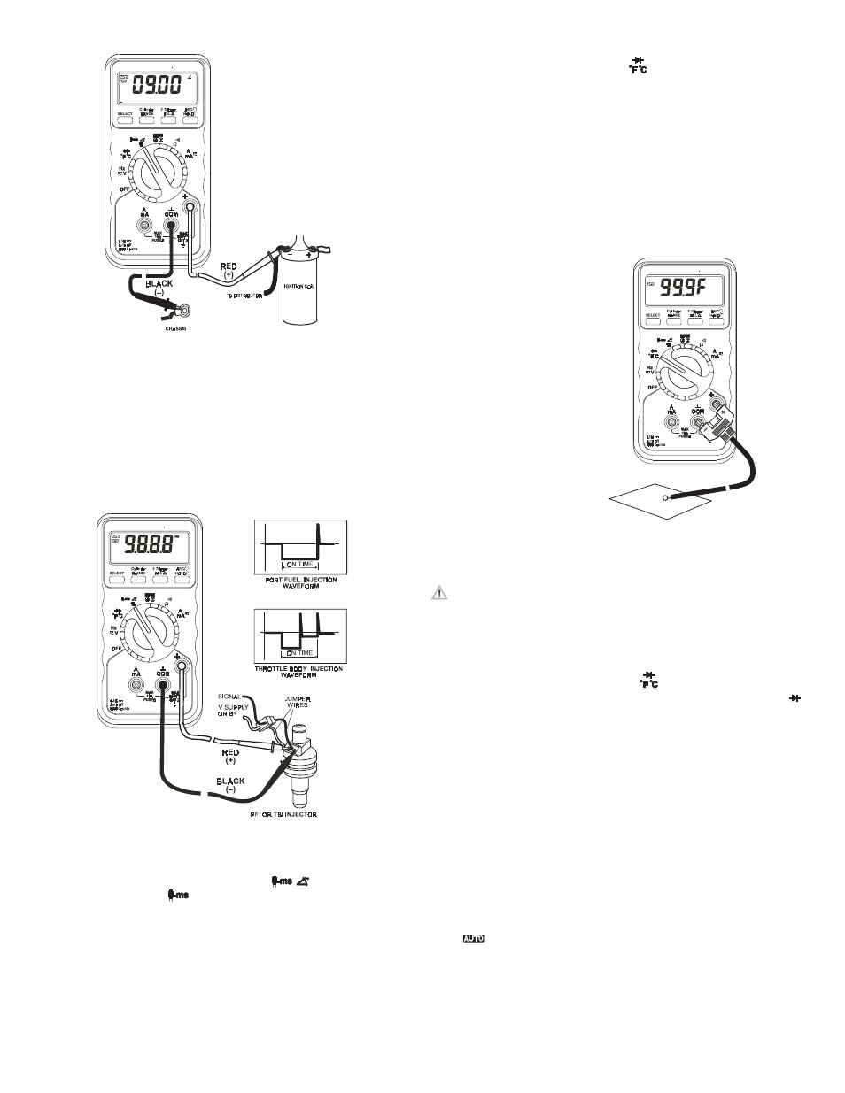
4.3.8 Temperature Measurement
•
Set the FUNCTION switch to the “
” position.
•
The instrument defaults to ºC units, to select ºF units press the
“SELECT” button once. To return to ºC units press the “SELECT”
button twice.
•
Connect the K-type thermocouple probe connector into the “COM”
and “
+
” sockets observing the polarity of the connector and
socket.
•
Make contact between the thermocouple at the end of the
probe the object to measure. To obtain accurate temperature
measurements, the contact between the probe and the object to
measure should be maintained for a few seconds until the readout
on the display becomes stable.
•
Connect the black test lead to the vehicle ground or negative (-)
terminal of the battery, and the red test lead to the breaker point of
the distributor or negative (-) terminal of the ignition coil.
•
To display Dwell as a percentage (%), press the “SELECT” button
once. To display reading in degrees again, press the “SELECT”
button twice.
•
To change the trigger level and slope please refer to Section 4.4.4
and 4.4.5 of this manual.
4.3.7 Fuel Injector (Pulse Width) Measurement
•
Connect the black test lead to the “COM” socket and red test lead
to the “
+
” socket.
•
Set the FUNCTION switch to the “
%” position, the
instrument default to
, with units in ms (milliseconds).
•
Connect the black test lead to the signal wire terminal of the fuel
injector, and the red test lead to the positive supply wire terminal of
the fuel injector.
•
To display pulse width as a percentage (%) or duty cycle, press
the “SELECT” button twice. To display reading in ‘ms’ units again,
press the “SELECT” button again.
•
This function applies to both Port Fuel Injectors (PFI) and Throttle
Body Injectors TBI). To change the trigger level and slope please
refer to Section 4.4.4 and 4.4.5 of this manual.
4.4 Other Functions
4.4.1 Diode Test
CAUTION: Maximum Input Voltage for this function is 600
Vrms, do not exceed this rating to avoid personal
injuries or damage to the instrument.
•
Connect the black test lead to the “COM” socket and red test lead
to the “
+
” socket.
•
Set the FUNCTION switch to the “
” position. The instrument
will default to temperature measurement in ºC units, to select
(diode test) press the “SELECT” button twice.
•
•
Forward voltage drop test: Connect the test leads across the
diode observing the polarity: red probe to the anode (+) of the
diode and black test lead to the cathode (-) of the diode under test.
The readout of a good silicon diode should be between 0.4 to 0.9
V. A readind outside this range may indicate a defective diode.
•
Reverse Voltage test: Connect the test leads across the diode
observing the polarity: red probe to the Catode (-) of the diode and
black test lead to the anode (+) of the diode under test. A diode in
good condition should produce a “
OL
“ reading, other reading may
indicate a damaged or defective diode.
4.4.2 Manual and Autoranging Operation
•
To lock the present range, press the “RANGE” button once, and
the
display indicator will turn off. Pressing the “RANGE” button
will step through the ranges. Pressing and holding the “RANGE”
button for 1 second or more will restore the meter to autorange
mode.
•
NOTE: When the instrument is in Record, Hold or Relative mode,
pressing the “RANGE” button will cause the meter to exit these
operations.
�����������
�����
������� �����
�����������
Measuring
Dwell
Measuring
Pulse Width on
EFI
systems
Measuring
Temperature