General Technologies ST05 Oxygen Sensor Tester and Simulator User Manual
Page 6
Page 10
Page 9
4. OxYGEN SENSOR INFORMATION
The oxygen sensor is one of the most critical parts of the emission control system and fuel
economy performance. This sensor measures the oxygen content in the exhaust gases,
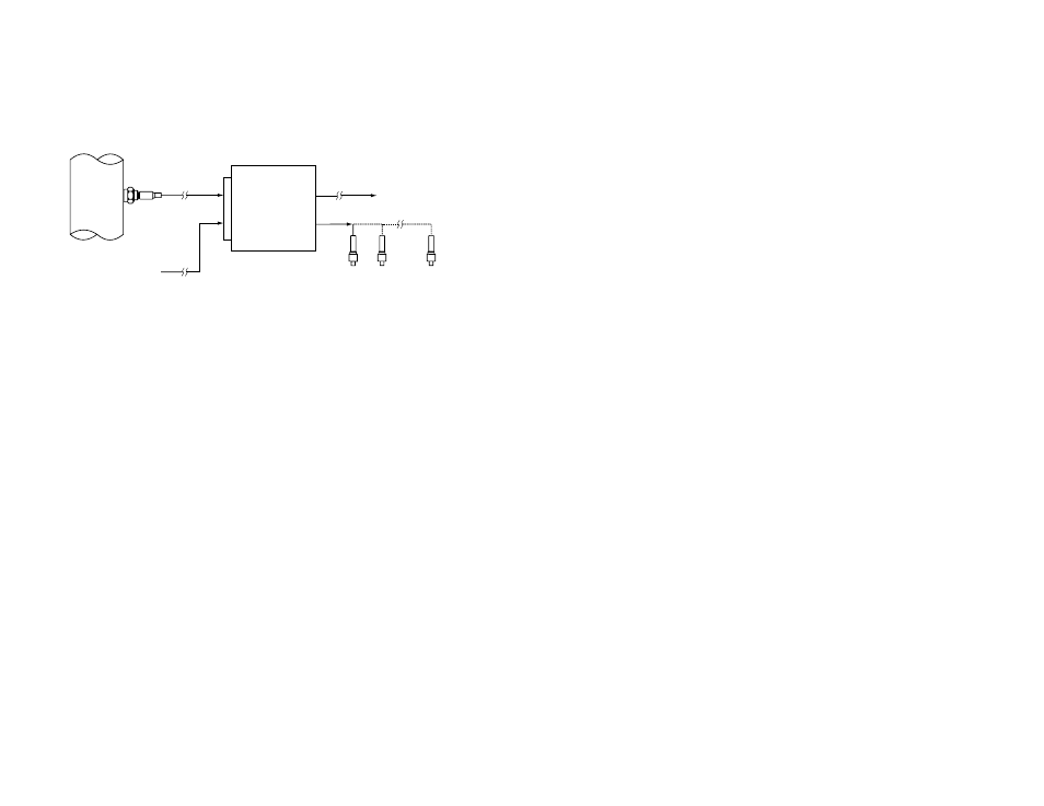
and the result is used by the PCM (Powertrain Control Module) to adjust the amount of
fuel injected into the cylinders. Optimization of the fuel/air mixture minimizes the emission
of pollutants and reduces fuel consumption.
Fig. 4 - Oxygen sensor function
A high content (excess) of oxygen in the exhaust gases is indicative of a lean fuel mixture,
which causes higher combustion temperatures responsible for producing pollutants like
NOx, and may even cause permanent damage to the engine.
Low oxygen content in the exhaust indicates a rich fuel mixture, which generates Carbon
Monoxide and Hydrocarbon (unburned fuel) emissions, and reduces fuel economy.
Additional oxygen sensors located after the catalytic converters, are used to measure the
converter’s efficiency, insuring they are working properly in reducing emissions. The
optimal Air/Fuel mixture ratio is 14.7/1 (weight ratio), and it is called ‘Stoichiometric’.
4.1 Oxygen sensor types
4.1.1 Zirconia (Zirconium)
This is the most commonly used type of sensor, and it is based on the properties of Zir-
conium Dioxide (ZrO
2
), which becomes conductive at high temperatures, allowing oxygen
ions through it, creating an electrical charge on a platinum plate. These electrical charges
generate the signal output for the sensor.
The most important characteristics of this type of sensor are:
1- Zirconia sensors do not require any external power or signals, they generate their
own voltage.
2- Unheated (one wire) and heated (2, 3 and 4 wire) versions are used.
3- The sensor will become active (generate a signal) at around 600 °F
(315 °C), but to give an accurate output, the sensor temperature has to be at
approximately 800 °F (425 °C).
4- These sensors require an external oxygen reference level, which is achieved by allow-
ing some ambient air into the sensor. In some of the older versions, a small hole in the
back was used to let air into one side of the sensing element. The most modern ones
use the sensor wires as air conduits for the same purpose.
5- Output signal levels: when operating the output signal should switch to 0.8 Volt or above
on the high side (rich mixture) and to 0.2 V or below on the low side (lean mixture).
At the optimal mixture for maximum efficiency, or stoichiometric point (14.7 fuel to air
ratio), the sensor output is approximately 0.45 Volt, so anything above this voltage will
be interpreted by the PCM as a rich mixture, and anything below as a lean mixture.
6- Response time: is the time it takes the sensor to change its output from below 0.175
Volts to above 0.8 Volts, in response to a sudden change in the fuel mixture from lean
to rich. The response time should be less than 100 ms, a longer transition time or not
reaching the voltage levels indicated, is indicative of a defective sensor.
4.1.2 Titanium (Titania)
This type of sensors uses the properties of Titanium Dioxide (TiO
2
), which changes its
electrical resistance in relation to the oxygen content of the exhaust gases. Titanium sen-
sors do not require an external oxygen reference level, therefore are immune to external
factors, like air pollution, or contamination like water.
The most important characteristics of this type of sensor are:
1- Titanium sensors require external power, which is either 1 Volt or 5 Volt depending on
the vehicle and manufacturer specification.
2- These sensors are all of the heated type.
3- In order to work properly, the temperature of the sensor must be between 800 and
900° F ( 426 and 500° C).
4- Output signal levels: these depend on the external voltage supply being used, for 1
Volt systems, the signal should switch from close to 0 Volts for Lean to near 1 Volt for
rich mixtures, with the stoichiometric level at 0.5 Volt. For 5 Volt systems, the output is
generally reversed, near 0 Volts output for rich mixtures and 5 Volt for lean mixtures,
with 2.5 as the stoichiometric level.
6- Response time: It is the time it takes the sensor to change its output from below 0.2
Volts to above 0.8 Volts, in response to a sudden change in the fuel mixture from lean
to rich. The response time (as in the Zirconia sensors) should be less than 100 ms, and
a longer transition time or small voltage swings are indicative of a defective sensor.
4.1.3 Wide Band (Air/Fuel Ratio) single cell sensors:
These sensors look like conventional Zirconia heated sensors, however a specialized circuit
in the PCM controls the current to and from the sensor to obtain a signal proportional to
the fuel mixture.
For testing of the sensor in the vehicle, it is necessary to disconnect the signal wires of
the sensor from the PCM to prevent the circuitry from interfering with the sensor’s signal,
but the heater wires must remain connected. Once the signal wires are disconnected,
this sensor will behave the same as a conventional Zirconia sensor. An alternative way to
test this sensor is to do an off vehicle testing, (refer to section “4.2.3 Off vehicle testing of
oxygen sensors”).
This sensor has been in use in some Toyota vehicles since 1996.
Powertrain
Control
Module
Oxygen
sensor
Other sensors
(MAF, MAP, TPS, etc.)
Fuel Injectors
Other systems
(Ignition module, etc
)