E-Mon 3208200W KIT User Manual
Page 8
3.0
Safety Label Defi nitions and Information
The Class 4000/4100 meter may contain one or more of the following labels.
Operator(s) should familiarize themselves with the meaning of each label to
minimize risk.
The presence of this label is a cautionary indicator
identifying a danger risk. The manual should be
consulted
prior
to
proceeding.
The presence of this label indicates an electrical
shock hazard exists in the location or area where
the label is placed. Prior to proceeding, the MAINS
power must be disconnected and the manual
consulted
for
safety
information.
4.0
Precautionary/Safety Information
WARNING:
High voltages present on main PCB terminal block TB1.
Risk of serious injury and/or electrical shock exists. Prior
to performing any wiring operations, review all contents of
the user manual and de-energize the MAINS power switch.
Only
qualifi ed personnel should perform installation
wiring. Installation wiring must comply with all local and
national
electrical
codes.
WARNING:
NEVER open front panel of unit while unit has MAINS
power applied. Failure to comply can increase the risk of
serious injury and/or electrical shock.
Page 5
5.0
Meter Installation
5.1
Mounting the Class 4000/4100 Meter
Use appropriately sized mounting hardware to fasten the Class 4000/4100
enclosure to the selected mounting surface. The four mounting holes are located
inside the enclosure and are accessed by removing the cover. The mounting
holes are centered 6 13/16” H x 4 13/16” W.
NOTE: Units must only be installed in indoor environments, where they will not
be affected by the elements.
5.2
Meter Board Connections
1. Wire
Entry:
Two 1/2” conduit openings are located on the back of the unit enclosure.
These openings are used for bringing in MAINS power and for current
sensor wiring. Route the appropriate cabling to and through the
respective enclosure opening.
After installing the conduit fi tting and conduit, verify that each conduit
slip nut is securely tightened to its respective conduit fi tting.
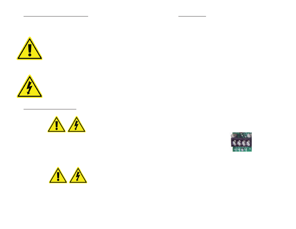
2.
Unit MAINS wiring:
The 4-position terminal block TB1, located at the bottom left corner of
the meter board, is clearly labeled A, B, C, N (neutral). AWG 14 or 12
gauge (stranded) conductors are typically utilized for this connection.
Figure 5.2.1.
Terminal
block
TB1.
A.
Connect the NEUTRAL wire to the appropriate terminal block position.
B.
On 2-wire, 120 VAC installations, connect the AC main power wire to the
Phase A position as labeled on terminal block TB1. On 3-wire 120/208
VAC installations connect the AC main power wires to Phase A and
Phase B positions on terminal block TB1. After all conductors are
connected to their respective terminal block positions and tightened
down, verify that each terminal block screw is securely fastened by
gently tugging on each conductor. Verify that no conductor wires
are frayed or shorting to adjacent terminal block positions.
Page 6