E-Mon 3208200W KIT User Manual
Page 7
5.2
Meter Board Connections (continued)
3.
External Switch Mechanism/In-Line Fuse Installation
To ensure a safe installation, the Class 4000/4100 requires an external
switch mechanism, such as a circuit breaker (max. 15 amps), be
installed to the Class 4000/4100 MAINS input wiring. The switch
mechanism must be installed in close proximity to the Class 4000/4100
and easily reachable for the operator. This device must also be marked
as the disconnecting device for the Class 4000/4100. Install 1/10 amp
Slow Activation inline fuses with the suitable voltage rating for
each conductor Phase at the MAINS input to the meter. The fuses must
be labeled to indicate voltage and current rating as well as element
characteristics. The fuse element must be slow activating type.
5.3
Current Sensor Installation & Wiring
The meter board contains two plug-in connectors located at the bottom center
of the board, TB2 and TB3. (See Figure 1.1.1) Connector TB2 is the input for
Phase A, and TB3 is the input for Phase B.
The Class 4000/4100 meter can be used with two types of current sensors:
1.
Split-core current sensor. This sensor opens so that it can be attached
around the circuit being monitored without interrupting power. Unless
otherwise
specifi ed, all Class 4000/4100 meters are supplied with this
sensor
type.
2.
Solid-core current sensor. This sensor does not open and requires the
monitored conductor to be removed from the circuit to install the current
sensor. This type is only supplied when specifi ed at time of order.
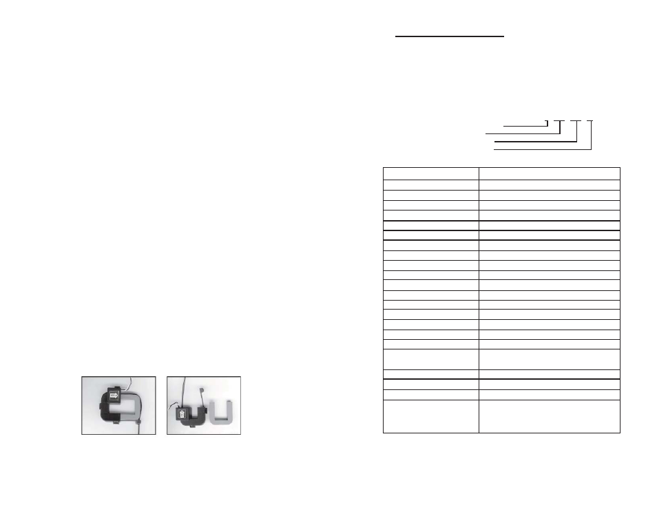
5.3.1
Installing the Split-Core Current Sensor Assembly
1.
Each phase being monitored will require one two-piece current sensor
assembly. Open the two-piece current sensor assembly by releasing
the nylon clamp using a fl athead screwdriver.
Page 7
2.0
Meter Technical Specifi cations
Ordering Information: Defi ne input voltage, current sensor rating and the RF
option, in the format C-xxx-yyyy-zz, where
C = number of conductors (2 or 3)
xxx=input voltage (120 or 208 [120/208/240])
yyy=current sensor rating (100, 200)
zz=designated option (W=none [Class 4000], WT (RF transceiver [Class 4100])
Example:
3 208 200 W
Number of conductors (3)
Input
Voltage
(208)
Current
Sensor
(200A)
RF
Transceiver
(none)
Input Voltage Confi guration
2-wire 120-volt, 3-wire 120/240-volt, 3-wire 120/208 volt
MAINS Voltage Input
Up to 240 VAC
Input Power
6 VA maximum rating
Current Sensor Rating
Up to 200 amps RMS AC available
Power Factor
0.5 leading or lagging
Line
Frequency
50-60
Hz
Metering
Accuracy
Certifi ed to ANSI C12.16 (+/-1% from 1-100% of rated load)
Voltage Operating Range
+/-10% of rated load
Temperature Range
-20 degrees C to +50 degrees C
Relative Humidity Range
0-95% non-condensing
Altitude
2000
meters
maximum
Voltage Overload
+25% continuously; +100% for 20 cycles
Current Sensor Overload
100% for 1 minute without damaging meter
Pollution Degree
Degree 2 in accordance with IEC 664
Installation (Overvoltage) Category
Category III
Measurement
Category
Category
III
Enclosure
Material
ABS
94VO
Display
Readout
6-digit
electro-mechanical
Standard Ranges
(2-wire)
120 VAC, 100, 200 Amp
(3-wire)
120/208/240
VAC,
100,
200
Amp
Modem
Interface
None
RS-485 Serial Communications
None
Load
Control
None
Recommended In-Line Fuse
Manufacturer: Littlefuse
Mfg Part No.: 313.100
Rating:
100mA, Slo-Blo, 250 VAC cartridge fuse
Table 2.0.1 Class 4000/4100 meter technical specifi cations.
Page 4