SPP Pumps Thrustream - Extended User Manual
Page 20
Manual No/Rev
W12-005E / 3
Operators Instructions for Horizontal
Extended Thrustream Centrifugal Pumps
Our policy is one of continuous improvement and we reserve the right to alter specifications at any time
Page 18 of 28
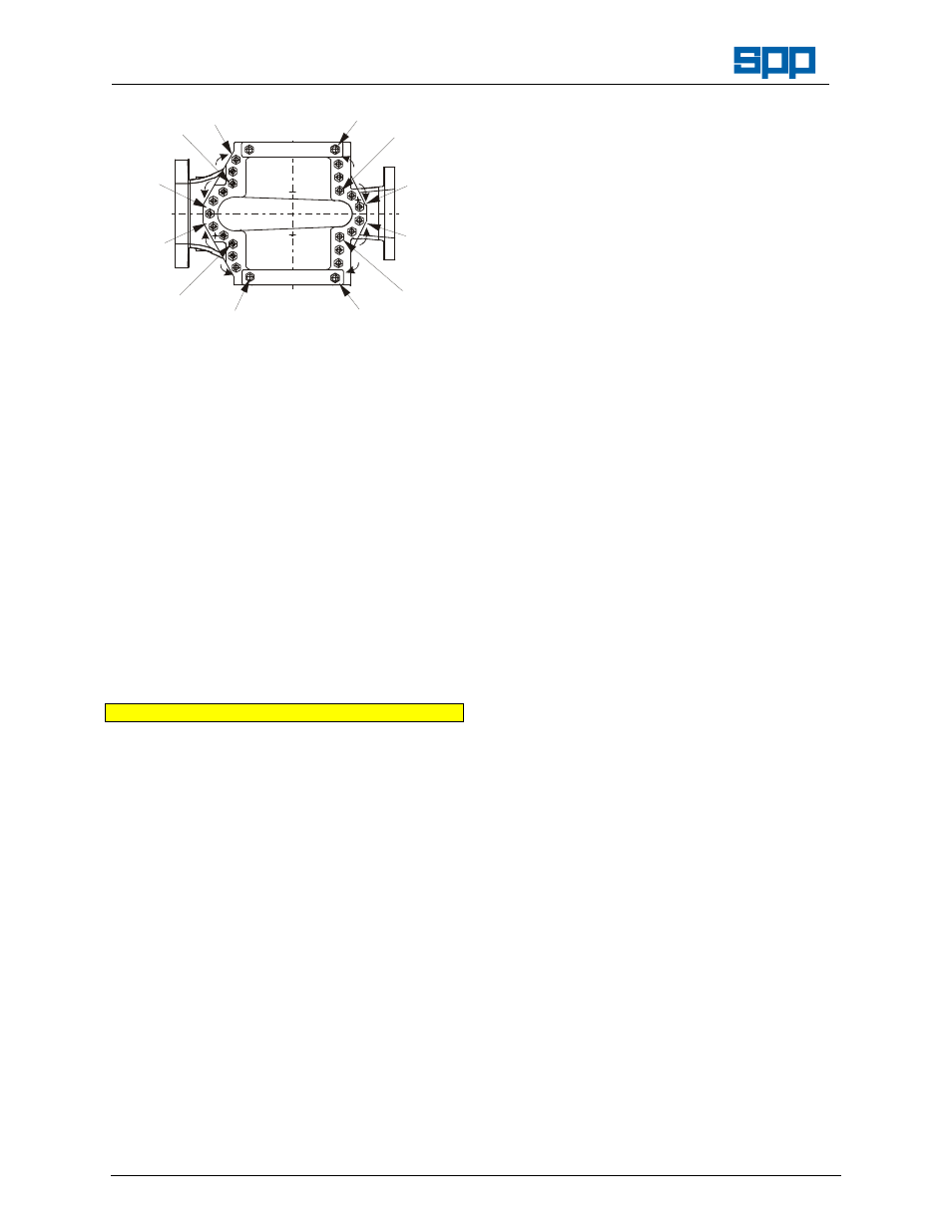
1
2
3
4
6
8
7
5
9
10
11
12
a) Tighten the four 'corner' screws marked 1,
2, 3 and 4.
b) Work outward along shaft axis toward the
stuffing
boxes
in
opposite
quarters
tightening screws in regions 5, 6, 7 and 8.
c) Work outward along the branch and in
opposite quarters tightening screws in
regions 9, 10, 11 and 12.
d) Repeat the whole sequence (a to d).
29. Check that the shaft turns freely by hand.
30. Top up the bearing lubrication by applying
several strokes with a grease gun.
31. The pump is now ready for re-coupling to the
motor and re-commissioning.
Two Stage Pump Assembly Instructions
Note: Two stage pumps are similar in construction
to the single stage pump and instructions
relating to maintenance and repair apply
equally to both types.
The difference relates to the disassembly of
the two impellers (A21 & B21) and the
interstage plate (8).
Proceed to disassemble the rotating assembly
as for single stage pumps to paragraph 10:
For Counter Clockwise pump construction:
16. Using a suitable ‘C’ spanner, unscrew and
remove the non-drive end sleeve (B47) on a
soft packed pump or impeller nut (A21) when
a mechanical seal is fitted.
For Counter Clockwise pump construction:
17. Using a suitable ‘C’ spanner, unscrew and
remove the drive end sleeve (A47) on a soft
packed pump or impeller nut (B21) when a
mechanical seal is fitted.
Note Light tapping with a soft faced mallet may be
needed to free the impeller from the shaft, do
not damage the impeller if it is to be reused.
1. Using suitable pullers or levers, slide the first
impeller (A21) of the shaft (71).
2. Withdraw the interstage plate (8) from the
impeller spacer (17) and check the condition
of the interstage neck bush (24) replace if
worn.
3. Tap and pull the other impeller (B21) off the
shaft with the impeller spacer (17).
4. Withdraw the impeller key (116) and unscrew
and remove the locked sleeve (A47) or the
impeller nut (B21).
Impeller re-assembly:
Proceed with shaft assembly as for single
stage pumps to paragraph 3.
1. Select the first impeller for assembly, check
the impeller for correct direction of rotation
and slide onto shaft to abut the locked sleeve
or nut.
2. Fit new O rings to each side of the impeller
spacer (17), slide on to the shaft and fit the
interstage plate (8) complete with its’ O ring,
ensuring that it is the correct way round to fit in
the pump casing.
3. Screw free impeller locking nut (A21) or
sleeve (B47) onto shaft to retain the impellers
against the locked impeller nut or sleeve.
4. Slide the casing wear rings (23) onto the
impeller.
5. Check that the dowels (8A) that retain the
interstage plate are correctly fitted.
Continue with pump re-assembly from
paragraph 7.