Perma Pure Baldwin-Series M325 User Manual
Page 6
Section C: Principle of Operation
6
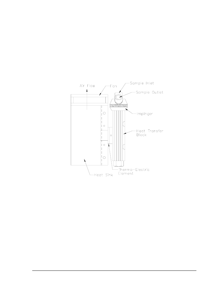
Figure 2: Heat Exchanger, Impinger and Heat Sink Assembly
316L stainless steel), PVDF (Kynar), or glass, is mounted within a thermally insulated heat
transfer block bored to receive the heat exchanger without a mechanical lock. This
assembly allows the easy removal of any heat exchanger simply by slipping it out of the
cooling block by hand. The heat transfer block cools the heat exchanger through the heat
pumping action of the peltier element. The heat transfer block is on the cold side of the
thermo-electric element and the heat sink is on the hot side of the thermo-electric element.
The heat from the heat transfer block is pumped to the heat sink where it is then dissipated
into the air by the heat sink fan. See Figure 2. The desired temperature is maintained by a
closed loop control system, which is implemented through an analog proportional controller.
The controller uses a type K thermocouple in the heat transfer block located very close to
the cold side of the peltier element as the input sensor.
The sample gas is passed to the thermo-electric cooler via the heated filter sample probe
and heated sample line. The thermo-electric cooler lowers the sample dew point to 5
°
C
(41
°
F). As the gas cools and the moisture vapor condenses, the condensate exits the heat
exchanger through the bottom drain connection. Particulate matter passing through the
sample cooler is removed by an optional Perma Pure pre-filter, located downstream from the
cooler along with an optional water slip sensor. The conditioned sample gas can then be
directed to the gas analyzers.