Multichannel Systems ADPT-NN-16-STIM User Manual
Page 2
ADPT-NN-16-STIM
16-Electrode NeuroNexus Probe
Adapter for MPA8I Amplifiers
with stimulation
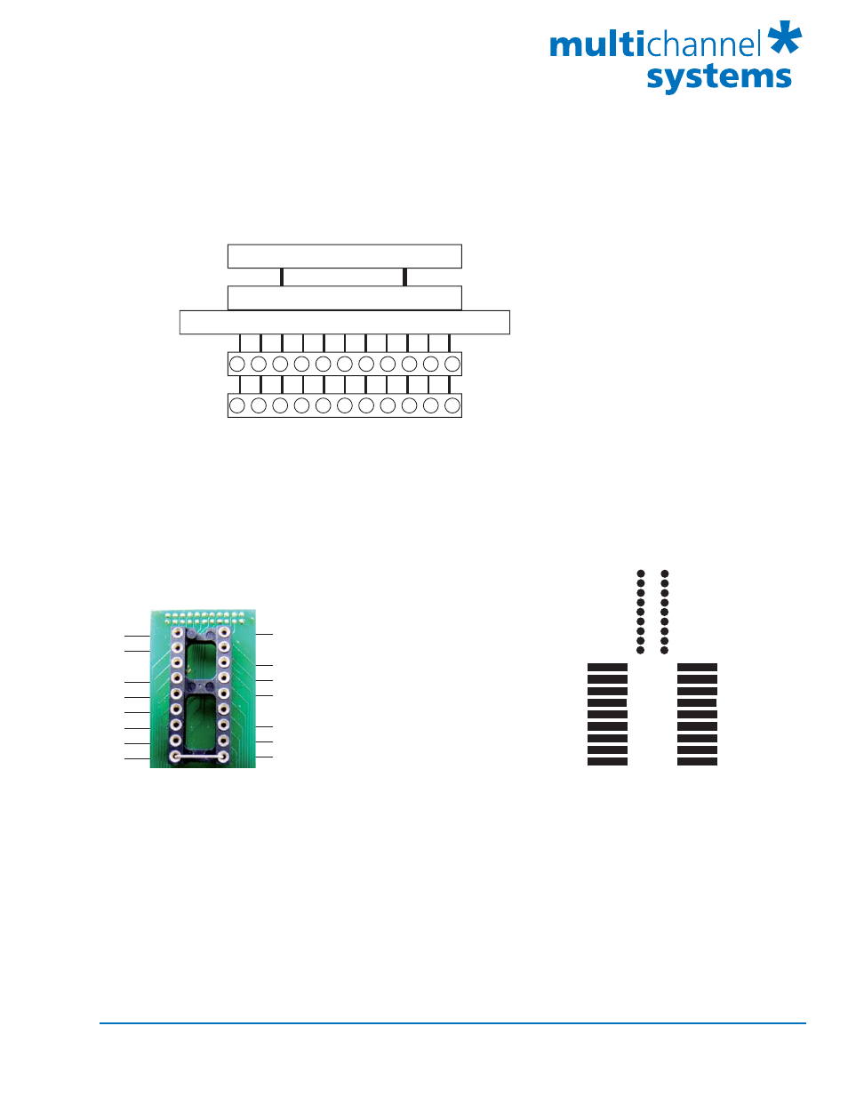
Connecting the NeuroNexus Probe to the ADPT-NN-16-STIM
Multi Channel Systems
MCS GmbH
Aspenhaustrasse 21
72770 Reutlingen
Germany
Fon +49-7121-9 09 25- 0
Fax +49-7121-9 09 25-11
[email protected]
www.multichannelsystems.com
© 201
2 Multi Channel Systems MCS GmbH
Product information is subject to change
without notice.
Shown are the output pins of the adapter that are connected to the miniature preamplifiers MPAI when
looking directly at the pins. The labelled channels are the ground channels (G), the reference channel (R),
and the 8 recording channels (1 to 8) of the MPA8I. Please see the MPA8I Manual for details.
Shown are on the left side the input pins of the adapter that are connected to the NeuroNexus probe.
The labelled channels are the ground channel (G), the reference channel (R), and the eight recording
channels (1 to 8) of the MPA8I. Please see the MPA8I Manual for details. G and R have been connected
together as factory-default settings. You can change this connection to meet your requirements.
On the right side you see the input pins connected to the NeuroNexus probe, and the correlating toggle
switches for stimulating one or more electrodes.
Pin Layout for MC_Rack:
MPA8I No. 1
MC_Rack
Pin 1 - 8
Channel 1 - 8
MPA8I
No.2
Pin 1 - 8
Channel 9 - 16
Note: Operation of the MPA8I is differential. The reference channel R has to be used
for obtaining a proper signal.
MPA8I
No. 1
8
7
6
5
4
3
2
1
G
MPA8I
No. 2
9
10
11
12
13
14
15
16
R
1
3
5
6
7
8
4
2
R
8
6
4
3
2
1
5
7
G
No. 2
MPA8I
MPA8I
No. 1
Channel assignment, input pins (connected to NeuroNexus Probe)
8
7
6
5
4
3
2
1
R
G
G
8
7
6
5
4
3
2
1
R
G
G
NeuroNexus Probe
NN-ADAPTER
MPA8I No. 1
MPA8I No. 2
Channel assignment, output pins (connected to the MPA8I)