Discontinued – Max Machinery 286-300 SERIES TRANSMITTERS User Manual
Page 7
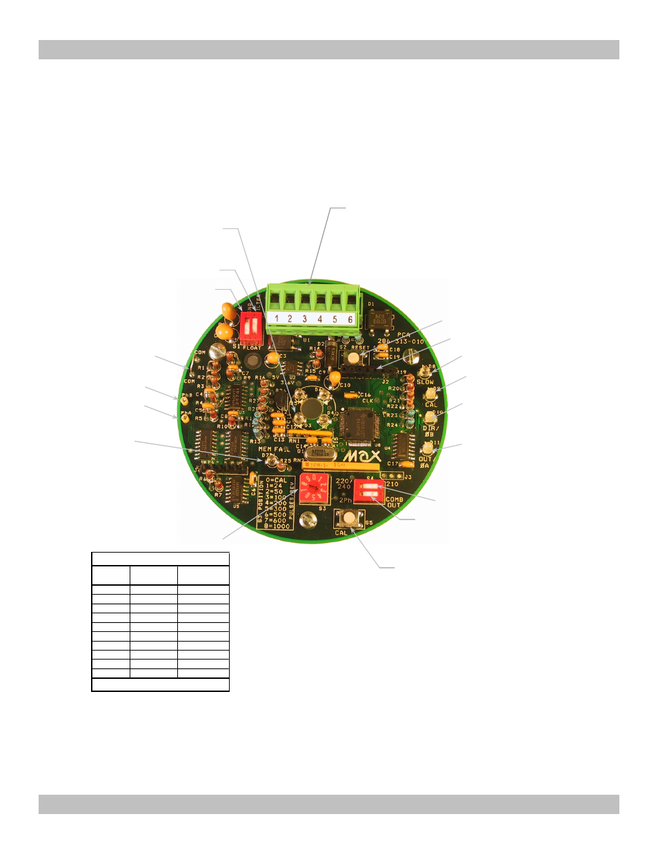
Output Frequency Select:
S3: Rotary switch allows selection of output resolutions of 24 to 1000 pulses per revolution (square
wave output), or 12 to 500 pulses per revolution (per phase) if the 2-phase output option is selected.
The resolution can be changed while the tachometer is operating, and the new value will take effect
immediately. See chart below for resolution at each switch setting.
J2: Header for Factory Programming Only
D10: Direction/Phase B (Terminal 6
Status) (High = Green, Low = Red)
*
D11: Output/Phase A (Terminal 4/5
Status) (High = Green, Low = Red)
S4-2: Output Select (2- Phase or Combined
Output) Assigns outputs of Terminals 4-6 and
D10 and D11.
S5: Calibrate Stator Offsets
(and Angle). Need S3 in
position 0 to start Calibration.
S3: Output Frequency Select
And Calibration Enable
D7: Microcontroller Memory
Status (On = Fail)
S4-1: Select Meter Type
Type
Stator Phase A Testpoint
Stator Phase B Testpoint
Common Testpoint
S1-1: Ground
S1-2: Filter
Terminal Block
1. Case (Green)
2. Common (Black)
3. Power 5-30VDC (Red)
4. Combined Output (White)
5. Phase A Out (Orange)
6. Phase B Out or Direction (Blue)
S2: Reset Microcontroller
D8: Flow too low to calibrate
D9: Calibration Active
D3-D6: RVDT Rotor Position
Indication (4 LED’s)
S3
2-Phase
Combined
Position
Output
Output
0
0 (Calibrate)
0 (Calibrate)
1
12
24
2
25
50
3
50
100
4
100
200
5
150
300
6
250
500
7
300
600
8
500
1000
9
*
*
Cycles per Revolution
* Not Specified, Usually same as S3=8
286-300-350 © 2002, Max Machinery, Inc.
Outputs, Options & Indicators
(7)
* Phase A leads Phase B when meter
is turning CCW (forward flow on
piston and gear style meters, reverse
flow on helix meters). Indicated at
terminal 6 by a 5 VDC signal and the
changing of D10 to green.
Discontinued