Reference diagram, I. installation, Important – Mach III Clutch 118FM & 118FM-ULOW User Manual
Page 2
7/10/2013
CLUTCH_SENSIFLEX_FM_MANUAL
Page 2 of 5
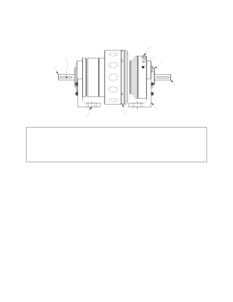
Reference Diagram:
AIR INLET
CYLINDER
ADJUSTMENT NUT
OUTPUT SHAFT
FOOT BRACKET (2)
MOUNTING SLOTS (4)
FRICTION LINING
INPUT SHAFT
KEY (2)
}
PISTON/DRIVE DISC
ASSEMBLY
I.
Installation
A. MOUNTING
SensiFlex® Foot Mounted clutches are designed to deliver long, maintenance free service. The
clutch has a designated input and output shaft (please refer to diagram above). Thermal horse-
power ratings are only valid if the clutch is oriented in this manner.
To achieve the smoothest performance and maximum bearing life, care should be taken during
installation to ensure accurate alignment.
1. The mounting surface for the clutch foot brackets must be flat.
2. The (4) mounting slots are provided to allow some axial adjustment. For best results, apply
air to the clutch before tightening the (4) mounting bolts to help maintain proper
positioning of the feet.
B. AIR LINE CONNECTION
Air supply should be both filtered and regulated. Contamination in the air supply will cause
damage to the clutch, particularly to the diaphragm actuator. Connect a flexible air line to
the air inlet using a thread sealing compound. Do not use rigid piping. Cycle the clutch
with the machine off to assure engagement and release.
**IMPORTANT**
The gap between the friction and drive surface is factory set between 0.010 and 0.020 Inch.
This is the ideal clearance for proper performance.
Increasing this gap may result in air leaks and damage to the diaphragm actuator.
Decreasing this gap prevents full disengagement of the clutch.