Lightronics AT402 User Manual
Page 2
Page
2
of
8
AT SERIES ARCHITECTURAL DIMMER
Revision 0.1
OWNERS MANUAL
08/29/2003
www.lightronics.com
Lightronics Inc.
509 Central Drive Virginia Beach, VA 23454
tel 757 486 3588
LOCATION AND MOUNTING
The unit is to be wall mounted using the mounting holes provided in the chassis. Orient the unit such that the
circuit board is in the lower left area of the chassis. The unit may (but is not required to be) spaced out from the
wall approx. 1 inch. This may be desirable if the unit must be used in a location with a high ambient temperature.
Standard sized knockout holes are provided in the top, bottom and right side of the chassis for wiring. Be sure
that the vent holes in the chassis and cover are not obstructed since they are needed for proper cooling.
INPUT POWER CONNECTIONS
WARNING
Make sure that all power is removed from feed circuits before proceeding with wiring.
Connect power input leads to the lower terminal strip positions as indicated on the terminal strip labels. A hot
feed line is needed for each channel. Associated NEUTRALS are to be connected to the NEUTRAL bar provided.
An earth ground is also needed. A ground lug is provided. The terminal strip connection torque specification is 16
lb.-in. max. The minimum wire size is AWG#12. Consult the applicable electrical codes for your location for exact
wire specifications. The power terminal connections are intended for copper wire only. This unit will work on
either single or three phase power. Any dimmer channel may get power from any phase.
LOAD CONNECTIONS
The AT Series dimmer is intended for incandescent lamp loads. You can connect up to 2400 Watts of lighting to
each channel. Connect lighting loads to the upper terminal strip positions as indicated by the label. The neutral
bar and ground lug may be used for lighting loads. The terminal strip connection torque specification is 16 lb.-in.
max.
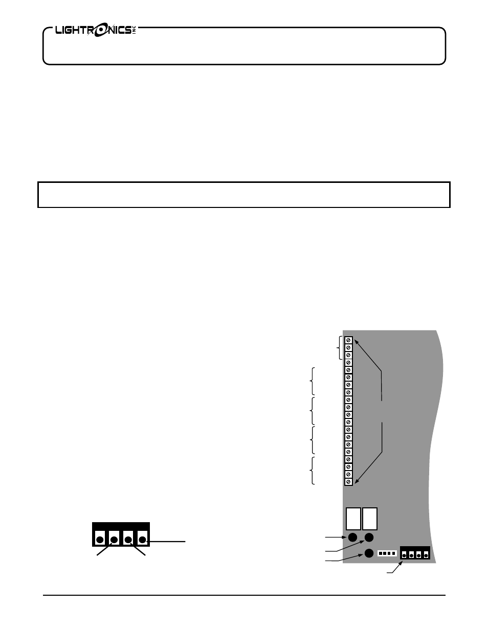
REMOTE SWITCH CONNECTIONS
A control terminal strip located on left side of
the low voltage section of the printed circuit
board is provided for connecting external switch
control signals. In general, a common signal
(circuit ground) is sent from the terminal strip to
a momentary contact of a remotely located
switch. The switch closure is returned to other
positions on the AT-402 dimmer control
terminal strip to activate four preset channel
intensity levels for each of 4 lighting conditions
to be activated.
DMX CONNECTIONS
A 4 pin screw terminal connector is provided for
DMX signal input. It is located aprox. centered
along the bottom edge of the circuit board. The
connection details are shown below:
Common
All On / Resume
Channel 4
Preset A
Preset B
Preset C
Preset D
CIRCUIT
CARD
Channel 3
Preset A
Preset B
Preset C
Preset D
Channel 1
Preset A
Preset B
Preset C
Preset D
Channel 2
Preset A
Preset B
Preset C
Preset D
A
1
NEXT
DOWN
UP
Control
Terminal Strip
DMX CONNECTOR
DMX DATA -
DMX DATA +
DMX COMMON