Programmable inputs and outputs wiring, Control system interconnections, Three programmable inputs – Lectrosonics DMPA12 User Manual
Page 9: 3 programmable outputs, Programmable inputs/outputs
DMPA12 Installation Guide
Rio Rancho, NM
9
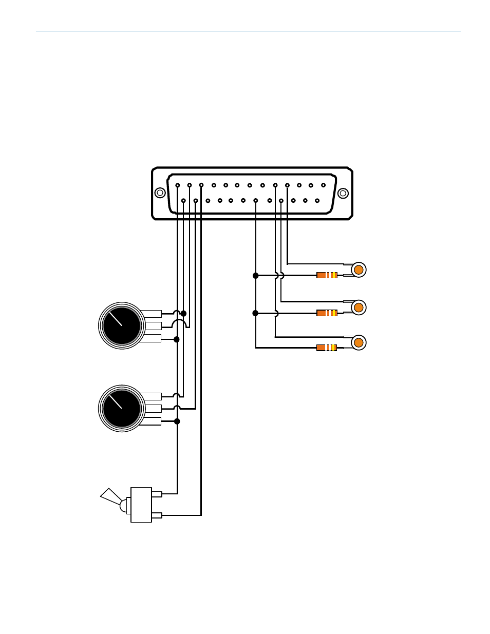
Programmable Inputs and Outputs Wiring
Remote control with external pots and switches is provided with Programmable Inputs on a standard DB-25 connector
on the rear panel. Programmable Outputs are used to provide external LED indicators and to trigger other events.
Examples of the wiring are shown below.
PROGRAMMABLE INPUTS/OUTPUTS
1 - GND
2 - IN 1
3 - IN 3
4 - IN 5
5 - IN 7
6 - IN 9
7 - IN 11
8 - GND
9 - OUT 1
10 - OUT 3
11- OUT 5
12 - OUT 7
13 - GND
14 - +5V
15 - IN 2
16 - IN 4
17 - IN 6
18 - IN 8
19 - IN 10
20 - +5V
21 - OUT 2
22 - OUT 4
23 - OUT 6
24 - OUT 8
25 +5V
1
13
ccw
cw
ccw
cw
ON
OFF
OUT 3
OUT 4
OUT 1
IN 1
IN 2
IN 3
500 Ohms
500 Ohms
500 Ohms
LED
LED
LED
Potentiometer
Potentiometer
Switch
Three Programmable Inputs:
2 - 10 K linear potentiometers
for volume control
1 - Tobble switch for muting
3 Programmable Outputs:
LEDS for function indicators
(380 to 500 Ohm resistors in-line
to avoid burning out LEDS)
NOTE
Common Connections can be used for
all voltage and ground connections
among all devices.
* Windows
Vista and XP or are trademarks of
Microsoft Corporation.