Front panel description, Quad uhf, Lectrosonics – Lectrosonics QUADUHFD User Manual
Page 4
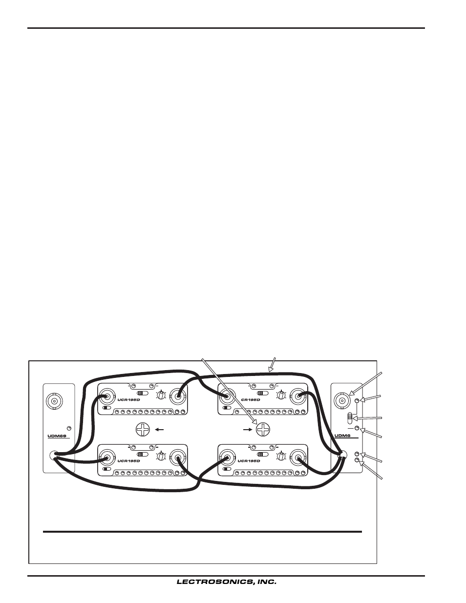
FRONT PANEL DESCRIPTION
ANTENNA LEADS - These BNC terminated leads provide isolated RF signals for each receiver installed in the
system.
ANTENNA - The antenna provided with the unit attaches to this BNC connector directly with a twist lock motion.
Other 50 Ohm antennas may also be used.
POWER SWITCH - The switch on the front panel of the UDM6 module controls the powering options:
In the EXT (upper) position, the unit will operate only from external power supplied to pins 1 and 4 of the rear panel
4-pin XLR connector.
In the OFF position, all power to the recievers and distribution modules is disconnected, however, the internal
batteries in the Quad Pak can still be charged with the CH80 charger connected to the rear panel 4-pin XLR connec
tor.
In the EXT OR BATT (lowest) position, the system is activated and power will be drawn power from either the gel-cell
batteries located in the bottom of the Quad Pak, or from an external 12 VDC power source if one is connected to the
rear panel 4-pin XLR jack. In this mode, the internal batteries act as a backup of the external power source. If the
voltage from the external power source drops to a level too low for operation, a built-in automatic relay will switch the
external power off and the internal gel-cell batteries on.
EXT LED - This LED will light when power is provided from an external 12 VDC power supply at the rear panel 4-pin
XLR connector.
BATT LED - This LED indicates operation from the internal gel-cell batteries.
CHARGE LED - This LED lights when the gel-cell batteries are being charged with the CH80 charger. It will extin
guish when the batteries achieve full charge.
AC LED - This LED indicates the unit is plugged into AC with the CH80 charger. It remains on as long as the
charger is connected, regardless of the battery charge state.
INSTALLATION SCREWS - These screws are used for receiver installation and removable. See RECEIVER IN
STALLATION for further instructions.
Installation Screws (2)
Antenna Leads - 4 Main, 4 Diversity
Charging LED
ANTENNA
POWER
LECTROSONICS
UHF RF
DISTRIBUTION
EXT
OFF
EXT
CHARGE
AC
ANTENNA
LECTROSONICS
UHF RF/POWER
DISTRIBUTION
EXT
OR
BAT
QUAD UHF
DIVERSITY
LECTROSONICS
TIGHTEN THESE SCREWS
AFTER INSTALLING THE RECEIVERS
MOD
1mV
10uV
-42
RF
1uV
-36 -30
POWER
INT
100uV
-12
-18
-24
-6
0dB
EXT
OFF
PILOT
0
180
MAIN
DIVERSITY
MOD
1mV
10uV
-42
RF
-36 -30
-12
-18
-24
-6
0dB
-42
-36 -30
-12
-18
-24
-6
0dB
1uV
POWER
INT
100uV
EXT
OFF
PILOT
0
180
MAIN
DIVERSITY
MOD
1mV
10uV
RF
1uV
POWER
INT
100uV
EXT
OFF
PILOT
0
180
MAIN
DIVERSITY
MOD
1mV
10uV
-42
RF
1uV
-36 -30
POWER
INT
100uV
-12
-18
-24
-6
0dB
EXT
OFF
PILOT
0
180
DIVERSITY
N
Antenna
Ext Power LED
Power Switch
Bat Power LED
AC LED
4