General technical description, General, Compandor noise reduction – Lectrosonics T6 User Manual
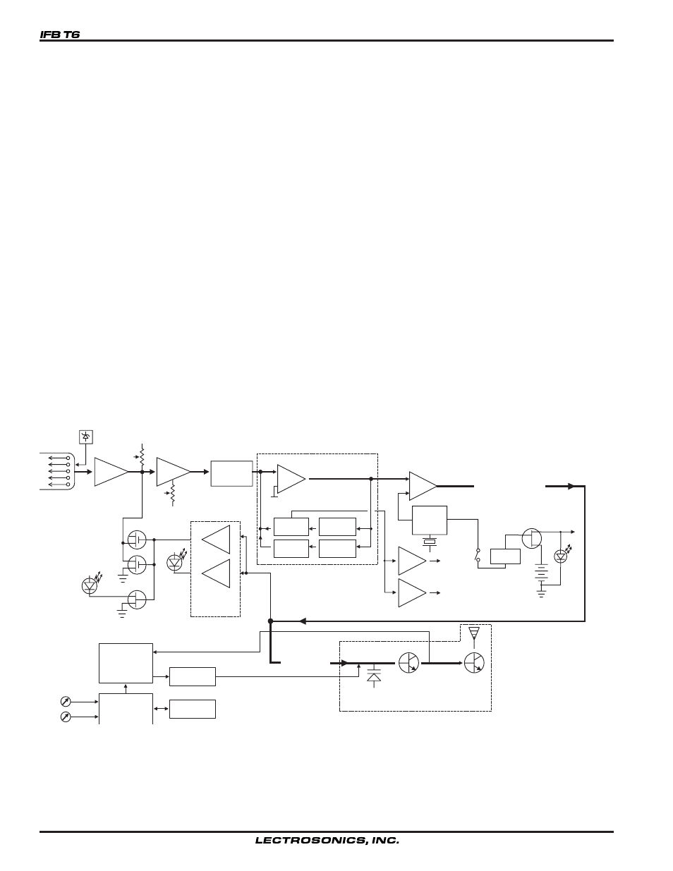
Page 4: Ifb t6 block diagram
GENERAL TECHNICAL DESCRIPTION
The IFB T6 transmitters are comprised of a number of functional sub-systems as shown in the block diagram below.
GENERAL
The system uses 20kHz wide deviation for high signal to noise ratio. The transmitter circuits are all regulated to allow
full output power from the beginning (9 Volts) to the end (6.5 Volts) of battery life. The input amplifier uses a Motorola
33178 op amp for ultra low noise operation. It is gain controlled with a wide range input compressor which cleanly
limits input signal peaks over 30dB above full modulation.
COMPANDOR NOISE REDUCTION
The single band compandor is a high quality audio device that processes the input signal such that the large dynamic
ranges of input signal can be transmitted to the receiver without overload or noise. A complementary system in the
receiver recovers the original dynamics of the signal for full audio quality. Compression and expansion ratios are
complementary at 2:1. High frequency pre-emphasis is implemented in the transmitter to provide another 10dB signal
to noise improvement. Matching de-emphasis is provided in all receivers.
TRANSMITTER
Vref
BASS
TREBLE
LP FILTER
HP FILTER
LIMIT
LED
COMPANDOR
Vreg
Vreg
+5VDC
+3.6VDC
SHUNT
LIMITER
INPUT
AMP
AUDIO
LEVEL
LP
FILTER
PEAK AUDIO
INDICATOR &
LIMITER
DRIVER
PILOT
TONE
OSC
5
4
3
2
1
MIC
JACK
+5V BIAS
SUPPLY
LF
ROLL-OFF
COMPANDED AUDIO
TO XMTR
COMPANDED
AUDIO
VOLTAGE
CONTROLLED
OSCILLATOR
FREQ
SWITCHES
LOW PASS
FILTER
BUFFER
PWR
DELAY
+9VDC
PWR
LED
SYNTHESIZER
uP
E PROM
2
SET
LED
IFB T6 Block Diagram
4