Controls and functions, External “p” switch – power on/off, A” switch – audio on/off – Lectrosonics UT200c User Manual
Page 5: Internal frequency adjust, Mod level leds, Audio level, External switches bypass, External led off
Frequency Agile Handheld Transmitter
CONTROLS AND FUNCTIONS
EXTERNAL
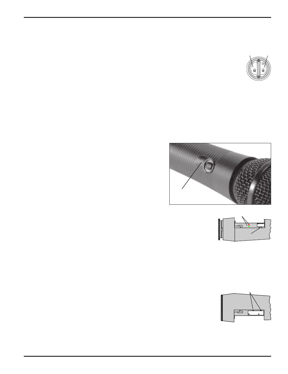
“P” SWITCH – POWER ON/OFF
Audio
Power
A slide switch which turns battery power on and off. The LED next to the switch lights up when the “P”
switch is turned on. This LED also serves as a battery condition indicator. The LED will glow brightly
when the battery is good and will dim as the battery condition deteriorates. The LED is at full brightness
with a new battery. When the battery voltage reaches 7 Volts, the LED will be completely dark. Note: this
LED will not light if the EXT LED switch is in the OFF position.
On/Off
On/Off
P
A
“A” SWITCH – AUDIO ON/OFF
A slide switch which “mutes” the audio in the OFF position and allows the audio gain (modulation level) of the trans
mitter to be adjusted without feedback from the sound system. This switch will do nothing if the EXTERNAL
SWITCHES switch is in the BYPASS position.
INTERNAL
FREQUENCY ADJUST
Two rotary switches adjust the center frequency of the carrier. The
1.6M is a coarse adjustment and the 100K is the fine adjustment.
Each transmitter is factory aligned at the center of its operating
range. The default position of the frequency select switches is in
the center of the transmitter’s range. See page 10 for details on
adjusting the transmitter frequency.
MOD LEVEL LEDs
These LEDs (located under the battery door) indicate the audio input level and are used
Mod Level
LEDs
Frequency switches
located behind door.
when adjusting the transmitter AUDIO LEVEL (gain) control. As the audio level increases,
first one LED lights. The other LED lights as the audio level reaches maximum modulation.
The LEDs are located underneath the battery cover, next to the AUDIO LEVEL control and
are easily viewed when holding the transmitter in a normally used position.
AUDIO
LEVEL
Gain Control
AUDIO LEVEL
This knob (also located underneath the battery door) is operated while speaking or singing into the transmitter to
adjust the audio gain of the transmitter for the correct amount of modulation. The LEDs located next to it indicate the
modulation level as the gain is adjusted. See page 6 for details on this very important adjustment.
EXTERNAL SWITCHES BYPASS
This concealed slide switch defeats the external switches on the bottom panel for applica-
Bypass Switches
tions where it is best that the user not be able to operate the power and mute switches. The
external switches are bypassed when this switch handle is moved toward the bottom of the
unit.
EXTERNAL LED OFF
EXTERNAL
SWITCHES
BYPASS
EXTERNAL
LED
OFF
This slide switch defeats the battery status LED on the bottom panel for applications where
the LED may be distracting. With this switch in the right-hand position, the power will
remain on and the transmitter operating, even though the power LED is off. The external
LED is disabled when this switch handle is moved toward the bottom of the unit.
Rio Rancho, NM - USA
5