Controls and functions, Input jack, Power on/off switch – Lectrosonics UM250c User Manual
Page 6: Power on led, Frequency select switches, Modulation leds, Audio level
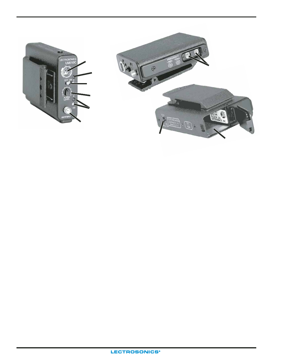
UM250C
Low Frequency Roll-Off
Adjustment (Under Cap)
Batter y Compartment
Frequency Select
Switches
INPUT JACK
The input on the UM250C accommodates virtually every
lavalier, hand-held or shotgun microphone available. Line
level signals can also be accommodated. Use a
Switchcraft TA5F connector on the cord. See the sepa
rate sheet titled “Transmitter 5-Pin Input Jack Wiring”
regarding the correct connections for various micro
phones, and other sources.
POWER ON/OFF SWITCH
Turns the battery power on and off. Even when the switch
is turned off or on abruptly, the pilot tone muting system
prevents “thumps” or transients from occurring.
POWER ON LED
Glows when the battery is good and the Power ON/OFF
switch is set to ON. A weak or dim LED means that the
battery is weak. When the LED goes out, there is about
15 to 30 minutes of operation left with alkaline batteries
and about 2 hours left with lithium. If the LED fails to
glow when the Power ON/OFF switch is set to ON, the
battery should be replaced.
The Power LED continuously monitors battery voltage. It
is at full brightness with a new 9 VDC alkaline or lithium
battery. As the battery voltage drops during use, the LED
brightness will also decrease. After about 7 hours of
operation (with a lithium battery) the battery voltage will
be about 7 Volts and the LED will be nearly out.
FREQUENCY SELECT SWITCHES
These two rotary switches adjust the center frequency of
the carrier. The 1.6M is a coarse adjustment and the
100K is the fine adjustment. Each transmitter is factory
aligned at the center of its operating range. The default
position is in the center of the transmitter’s range.
CONTROLS AND FUNCTIONS
Since the internal circuits are all tightly regulated and the
RF output stage has a separate discrete regulator, the
transmitter will continue to operate to a battery voltage of
7 VDC. As the voltage drops to 6 VDC, the transmitter
will still operate, but with degraded performance.
Note
A weak battery will sometimes light the POWER LED immediately
after turn on, but will soon discharge to the point where the LED will
go out, just like a flashlight with “dead” batteries.
The combination of an accurate battery condition indicator
and regulation of all internal circuits provides much longer
battery life, as well as consistent performance over the
life of the battery.
MODULATION LEDS
Indicates the audio modulation level set by the MIC
LEVEL control.
“-20” LED
Flickers or glows when sufficient audio
is present.
“0” LED
Lights up when the input level is high
enough to cause limiting. The input
limiter has a very high overload thresh
old (over 30 dB).
Generally speaking, some limiting is desirable in normal
operation to improve the signal to noise ratio of the
system. The limiting action is not audible and does not
create distortion. A highly trained ear would hear only the
compression of the peaks in the audio signal, which is
desirable with most tape recorders and many sound
reinforcement systems.
AUDIO LEVEL
Used to adjust the audio input level for the proper modula
tion.
Input Jack
Power ON/OFF
Switch
Power ON/O
AUDIO LEVEL
Control
Modulation LEDs
ANTENNA Connector
Power LED
6