Um190 input jack wiring, M190 transmitter equivalent input circuit – Lectrosonics UM190 User Manual
Page 8
UM190 INPUT JACK WIRING
The wiring diagrams shown on the separate sheet represent the basic wiring necessary for the most common types
of microphones and other audio inputs. Some microphones may require extra jumpers or a slight variation on the
diagrams shown.
It’s virtually impossible to keep completely up to date on changes that other manufacturers make to their products.
It is possible that you may encounter a microphone that differs from these instructions. If this occurs please call
our toll-free number listed in the back of this instruction manual. Our service department can answer your
questions regarding microphone compatibility.
When used on a wireless transmitter, the microphone element is in the proximity of the RF coming from the
transmitter. The nature of electret microphones makes them sensitive to RF, which can cause problems with the
microphone/transmitter compatibility. If the electret microphone is not designed properly for use with wireless
transmitters, it may be necessary to install a chip capacitor in the mic capsule or connector to block the RF from
entering the electret capsule. This modification is shown on the separate sheet titled "UM190 INPUT JACK
CONFIGURATION."
Our VHF transmitters uses the shield of the microphone cord as the antenna. The UM190 UHF transmitter uses a
1/4 wave flexible wire to radiate the RF signal. There is really not much difference between these two approaches,
with respect to the effect of the RF on the microphone capsule. Even in transmitters that utilize a "dangling wire,"
the microphone is still part of the "ground plane" and is therefore still in the antenna circuit.
5.1VDC
1K
1K
330
MPF480'S
7
22K
.22M
1uH
3.3M
10K
1K
5
33M
510
4
6
2
3
4
3
2
1
60NH
5321
1N
-
+
330PF
330PF
4
3
2
1
5
LECTROSONICS
+
+
+
Vcc
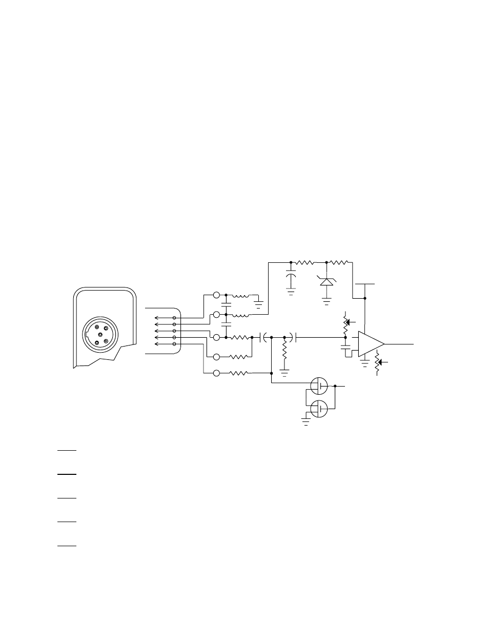
M 190
M190 TRANSMITTER
EQUIVALENT INPUT CIRCUIT
1 - NEG GND (OR BIAS)
2 - POS BIAS (OR GND)
3 - MIC
4 - SOURCE LOAD
5 - LINE IN
TO
AUDIO
CIRCUITS
MIC
GAIN
TO
LIMITER
CONTROL
LF
CUT
Figure 5 - M190 Input Connector and Schematic
PIN 1
Shield (ground) for positive biased electret lavalier microphones. Bias voltage source for negative biased
electret lavalier microphones. Shield (ground) for dynamic microphones and line level inputs.
PIN 2
Shield (ground) for negative biased electret lavalier microphones. Bias voltage source for positive biased
electret lavalier microphones.
PIN 3
Low impedance microphone level input for dynamic microphones. Also accepts hand-held electret
microphones provided the microphone has its own built-in battery.
PIN 4
1K Ohm source load for non-Lectrosonics electret microphones. Use in conjunction with other pins to
provide attenuation of high level input signals.
PIN 5
High impedance, line level input for tape decks, mixer outputs, musical instruments, etc.
7