General technical description, Frequency agile plug-on uhf transmitter, General – Lectrosonics UH200d User Manual
Page 3: Dual band compandor, No pre-emphasis/de-emphasis, Pilot tone squelch, Wide-band deviation, Long battery life, Frequency agility, Uh200d block diagram
Frequency Agile Plug-on UHF Transmitter
GENERAL TECHNICAL DESCRIPTION
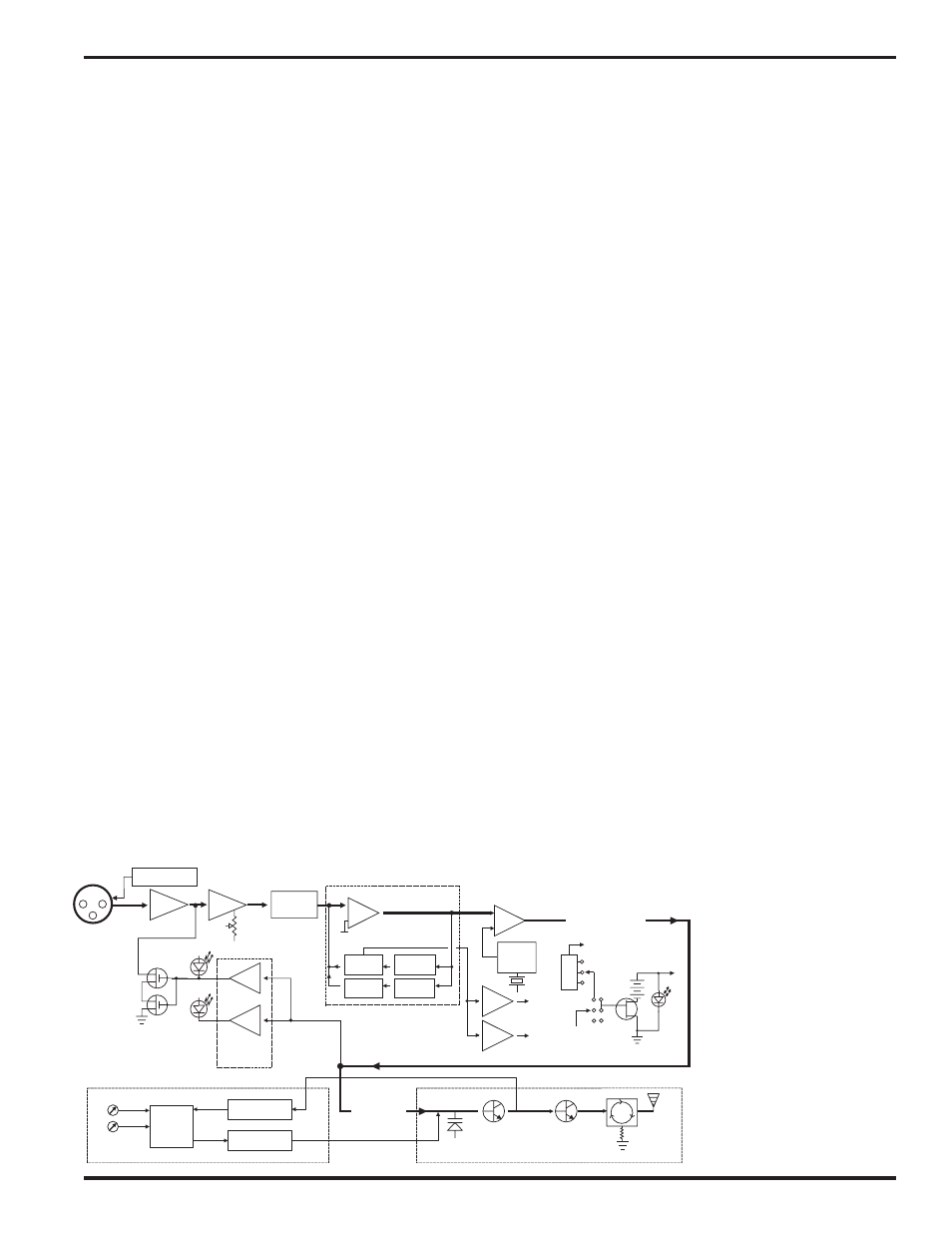
The UH200D transmitters are comprised of a number of func
tional subsystems as shown in the block diagram below.
GENERAL
The 200 system uses 75kHz wide deviation for an extremely high
signal to noise ratio. The transmitter circuits are all regulated to
allow full output power from the beginning (9 Volts) to the end
(6.5 Volts) of battery life. The input amplifier uses an ultra low
noise op amp. It is gain controlled with a wide range input
compressor which cleanly limits input signal peaks over 30dB
above full modulation.
DUAL BAND COMPANDOR
Traditionally, compandors have been a source of distortion in
wireless microphone systems. The basic problem with conven
tional systems is that the attack and decay times are always a
compromise. If the time constants are fast, high frequency
transients will not be distorted, but this will cause low frequency
distortion. If the time constants are slower, low frequency audio
distortion will be low, but high frequency transients will then be
distorted. The 200 system introduces an entirely new approach
to solving this basic problem, called “dual-band companding.”
There are actually two separate compandors in the 200 system,
one for high frequencies and one for low frequencies. A cross
over network separates the frequency bands at 1kHz with a 6dB
per octave slope, followed by separate high and low frequency
compandors. The attack and release times in the high frequency
compandor are fast enough to keep high frequency transient
distortion at a low level, and the low frequency compandor uses
slower time constants, reducing low frequency distortion to well
below that of a conventional compandor.
NO PRE-EMPHASIS/DE-EMPHASIS
The signal to noise ratio of the 200 system is high enough to
preclude the need for conventional pre-emphasis (HF boost) in
the transmitter and de-emphasis (HF roll off) in the receiver. Pre-
emphasis and de-emphasis in an FM radio system usually
provides about a 10dB improvement in the signal to noise ratio of
the system, but the high frequency boost in the transmitter must
be removed in a purely complementary manner or else the
frequency response of the original audio signal will be altered.
Pre-emphasis can also cause distortion in the receiver. As this
signal is passed through the IF filters in the receiver, distortion
POWER
+9VDC
TRANSMITTER
Vref
BASS
TREBLE
LP FILTER
HP FILTER
SET
LED
LIMIT
LED
COMPANDOR
Vreg
Vreg
+5VDC
+3.6VDC
SHUNT
LIMITER
INPUT
AMP
AUDIO
LEVEL
LP
FILTER
PEAK AUDIO
INDICATOR &
LIMITER
DRIVER
COMPANDED AUDIO
TO XMTR
PWR
LED
COMPANDED
AUDIO
PHASE LOCKED LOOP
VOLTAGE
CONTROLLED
OSCILLATOR
FREQ
SWITCHES
DIVIDER
LOW PASS
FILTER
PRESCALER
INPUT
JACK
+5V / +15V / +48V
BIAS SUPPLY
BUFFER
50
ISOLATOR
48V
5V
15V
BIAS
TO INPUT JACK
PILOT
TONE
OSC
can be produced, most noticeable at full modulation. De-empha
sis cannot be applied until the signal is converted into audio, so
there is no way around this problem short of eliminating pre-
emphasis altogether. Neither of these problems occur in the 200
system. The dual-band compandor in the 200 Series system
essentially provides a dynamic pre-emphasis/de-emphasis func
tion with extremely low distortion.
PILOT TONE SQUELCH
The 200 system utilizes an ultrasonic tone modulation of the
carrier to operate the receiver squelch. This “pilot tone” consists
of a 32kHz signal mixed with the audio signal after the compandor,
to control the audio output muting of the receiver. The pilot tone
is filtered out of the audio signal immediately after the detector in
the receiver so that it does not influence the compandor or
various gain stages. The basic benefit of the pilot tone squelch
system is that the receiver will remain muted until it receives the
pilot tone from the matching transmitter, even if a strong RF
signal is present on the carrier frequency of the system. This is
extremely important in applications that include an automatic
microphone mixer.
WIDE-BAND DEVIATION
±75kHz deviation improves the capture ratio, signal to noise ratio
and AM rejection of a wireless system dramatically, compared to
the more commonly used ±15kHz deviation.
LONG BATTERY LIFE
High efficiency circuits throughout the design allow over 4.5
hours of operation using a single 9 Volt alkaline battery. (A 9V
lithium battery will provide over 12 hours of operation.) The
battery compartment is a unique mechanical design which auto
matically adjusts to fit any brand of battery. The battery contacts
are spring loaded to prevent “rattle” as the unit is handled. The
battery life will be affected by the amount of phantom power
supplied to any microphones that require it. A high drain 48 Volt
microphone can shorten battery life by 40% or more. A light drain
15 Volt microphone will make little or no difference in battery life.
The only way to be sure is to test the transmitter and microphone
combination with a brand new battery; then and only then will you
be sure of the combination's battery life.
FREQUENCY AGILITY
The transmitter section uses a synthesized, frequency selectable
main oscillator. The frequency is extremely stable over a wide
temperature range and over time.
Two rotary switches, located
on the side panel of the unit,
provide 256 frequencies in
100kHz steps over a 25.5MHz
range. This alleviates carrier
interference problems in mo
bile or travelling applications.
UH200D Block Diagram
Rio Rancho, NM – USA
3