General technical description, Portable wireless sound system, Rio rancho, nm – usa 3 – Lectrosonics UH195 User Manual
Page 3
Portable Wireless Sound System
GENERAL TECHNICAL DESCRIPTION
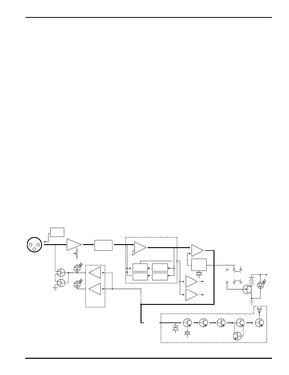
The UH195 transmitter is comprised of a number of functional sub-systems as shown in the block diagram below.
The 195 system uses 75kHz wide deviation. The transmitter circuits are all regulated to allow full output power from
the beginning (9 Volts) to the end (7 Volts) of battery life. The oscillator crystal is shock mounted to provide rugged
ness. The input amplifier uses a Motorola 33078 op amp for ultra low noise operation. It is gain controlled with a
wide range input compressor which cleanly limits input signal peaks over 40dB above full modulation.
The 195 system utilizes an ultrasonic tone modulation of the carrier to operate the receiver squelch. This “pilot tone”
consists of a 33kHz signal mixed with the audio signal following the microphone preamp, just after the compandor, to
control the audio output muting of the receiver. The pilot tone is filtered out of the audio signal immediately after the
detector in the receiver so that it does not influence the compandor or various gain stages. The basic benefit of the
pilot tone squelch system is that the receiver will remain muted until it receives the pilot tone from the matching
transmitter, even if a strong RF signal is present on the carrier frequency of the system. This is extremely important
in applications such as with an automatic sound system.
Traditionally, compandors have been a source of distortion in wireless microphone systems. The basic problem with
conventional systems is that the attack and decay times are always a compromise. If the time constants are fast,
high frequency transients will not be distorted, but this will cause low frequency distortion. If the time constants are
slower, low frequency audio distortion will be low, but high frequency transients will then be distorted. The 195
system introduces an entirely new approach to solving this basic problem, called “dual-band companding.”
There are actually two separate compandors in the 195 system, one for high frequencies and one for low frequen
cies. A crossover network separates the frequency bands at 1kHz with a 6dB per octave slope, followed by separate
high and low frequency compandors. The attack and release times in the high frequency compandor are fast enough
to keep high frequency transient distortion at a low level, and the low frequency compandor uses slower time con
stants, reducing low frequency distortion to well below that of a conventional compandor.
MIC
JACK
+5V BIAS
Vref
BASS
TREBLE
LP FILTER
HP FILTER
SET
LED
LIMIT
LED
COMPANDOR
Vreg
Vreg
+5VDC
+3.6VDC
COMPANDED
AUDIO
XTAL OSC
X4
X2
X2
X2
UHF TRANSMITTER
+9VDC
PWR
LED
SHUNT
LIMITER
+5V
-9V
ON
MUTE
DELAYED
OFF
SUPPLY
INPUT
AMP
AUDIO
LEVEL
LP
FILTER
PILOT
TONE
OSC
Peak Audio
Indicator &
Limiter Driver
Rio Rancho, NM – USA
3